XT-3 Reader Installation Manual & Data Sheet Doc no. 11-267 02
© TagMaster NA 17 (28)
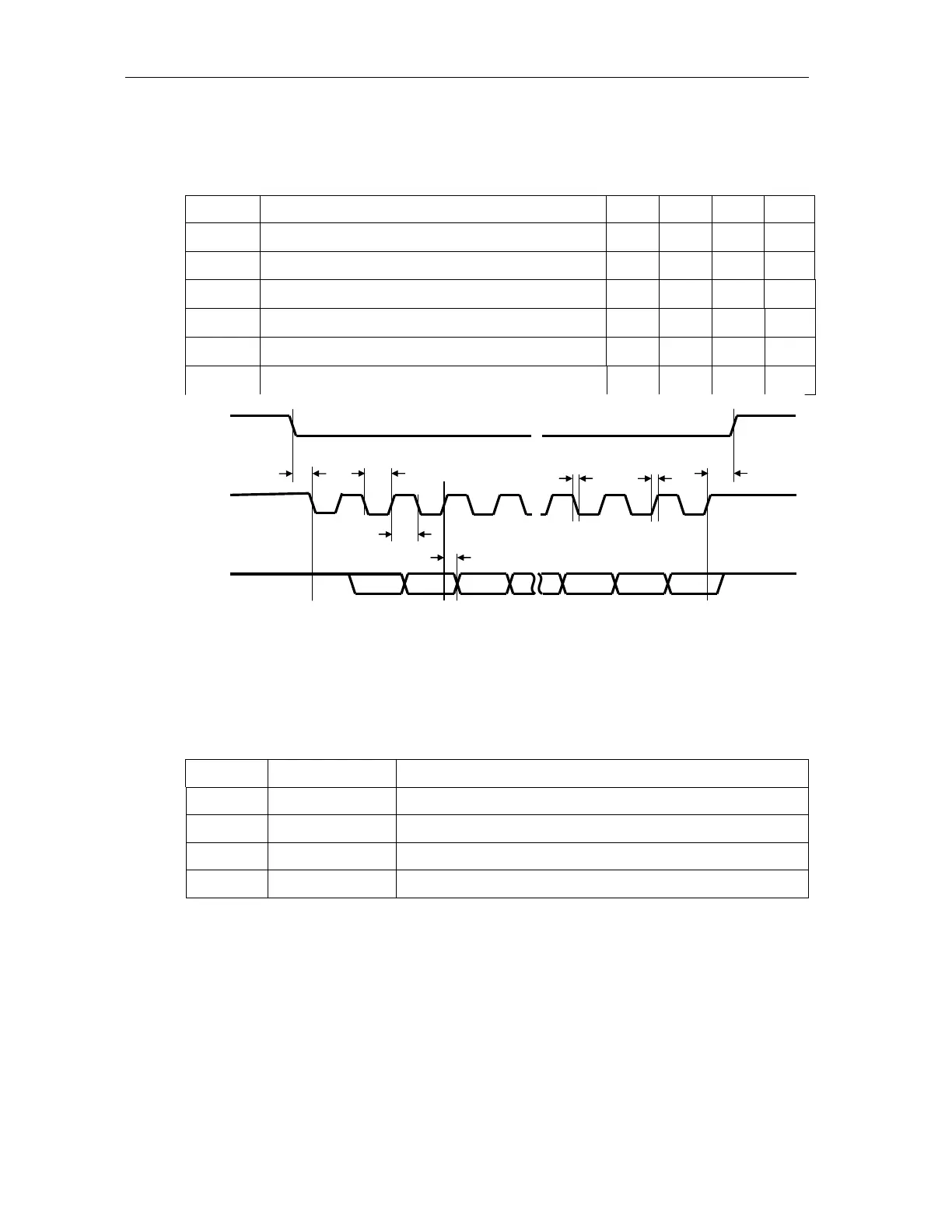
5.2.3.4 Mag-stripe Timing
The following values apply when all outputs are pulled up to 5V with 1kΩ resistors.
Table 7 Mag-stripe interface timing
Symbol
Parameter Min Typ Max Unit
t
SU
LOAD to CLK setup time 0
µs
t
F
Fall time (all signals) 125 ns
t
R
Rise time (all signals) 5
µs
t
CL
Clock low 150
µs
t
CH
Clock high 150
µs
t
H
LOAD hold time after last CLK change 0
µs
≈
≈
t
SU
LOAD
CLK
DATA
≈
t
CL
t
CH
t
DH
t
H
t
R
t
F
Figure 7 Mag-stripe timing diagram
5.2.4 Power Supply, Group J31
Pin 1 is internally connected to pin 3 and pin 2 is internally connected to pin 4. The
purpose is to make it possible to feed power to any peripheral equipment. Use pins 1
and 2 for power supply connection.
Table 8 Power Supply, Group J31
Pin Signal Description
1 SPL Positive DC supply input
2 RTN SPL Negative DC supply input
3 SPL Positive DC supply input, internally connected to pin 1
4 RTN SPL Negative DC supply input, internally connected to pin 2
5.2.5 Not used, Group J32
This group is not used.
5.2.6 RS485 Serial Communication Interface, Group J41
The controller board has one RS485 serial interface for both 2-wire and 4-wire
communication. RS485 supports multi-drop serial networks. The communication can
be in both full duplex (4-wire) and half duplex (2-wire).
Note: If the installation requires long cables or high data speeds it may be necessary to
use termination.