XT-3 Reader Installation Manual & Data Sheet Doc no. 11-267 02
© TagMaster NA 18 (28)
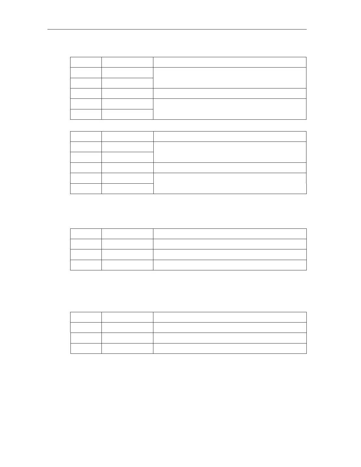
Table 9 Full Duplex (4-wire) RS485 Serial Communication Interface, Group J41
Pin Signal Description
1 TX+
2 TX−
Transmitted data, from reader to host
3 GND Ground
4 RX+
5 RX−
Received data, to reader from host
Table 10 Half Duplex (2-wire) RS485 Serial Communication Interface, Group J41
Pin Signal Description
1 TX/RX+
2 TX/RX−
Transmitted and received data, to and from Host
3 GND Ground
4 NC
5 NC
Not used
5.2.7 RS232 Serial Communication Interface, Group J42
The controller board has one RS232 serial interface.
Table 11 RS232 serial communication interface, Group J42
Pin Signal Description
1 TX Transmitted data, from reader to host
2 RX Received data, to reader from host
3 GND Ground
5.2.8 Service Interface, Group J43
The service interface is used for maintenance and configuration of the reader. Do not
use the service interface as a regular system interface.
Table 12 Service Interface, Group J43
Pin Signal Description
1 TX Transmitted data, from reader to host
2 RX Received data, to reader from host
3 GND Ground