Do you have a question about the Taie FY400 and is the answer not in the manual?
Essential safety guidance covering electric shock, installation, environment, and wiring.
Technical specifications for FY series controllers covering voltage, power, memory, input, output, control, alarms, etc.
Technical specifications for FA series controllers covering voltage, power, memory, input, output, control, alarms, etc.
Illustrates terminal connections for power, output, communication, and input for the FY400.
Illustrates terminal connections for power, output, communication, and input for the FY600.
Illustrates terminal connections for power, output, communication, and input for the FY700.
Illustrates terminal connections for power, output, communication, and input for the FY800.
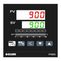
Illustrates terminal connections for power, output, communication, and input for the FY900.
Illustrates terminal connections for power, output, communication, and input for the FA230.
Illustrates terminal connections for power, output, communication, and input for the FA231.
Steps for performing automatic tuning to set PID parameters.
Explains how PV bias (PVOS, PVOH) corrects sensor deviations and inter-controller differences.
Explains the function that monitors heater current and detects disconnections or reductions.
Explains how the controller manages motor valves for fluid flow regulation based on output.
Details the programmable ramp and soak feature for controlling temperature profiles over time.
Details the 19 available alarm modes for system protection and application needs.
Flowchart for calibrating the 4mA~20mA output signal of the controller.
Step-by-step guide for calibrating low-point (CLO1) and high-point (CHO1) values for linear output.
Instructions for configuring the controller for thermocouple input, including calibration.
Instructions for configuring the controller for RTD input, including calibration.
Instructions for configuring the controller for linear 4-20mA input, including calibration.
Detailed steps for calibrating ANL1, ANH1, and DP for linear input signals.
| Brand | Taie |
|---|---|
| Model | FY400 |
| Category | Controller |
| Language | English |