Do you have a question about the Taie FU86 and is the answer not in the manual?
Contains critical safety warnings about electric shock and correct operation procedures.
Provides crucial precautions for safe power transmission and wiring to avoid damage.
Illustrates the terminal connections for power supply, outputs, alarms, communication, and inputs for FY400/FU400/FU48.
Illustrates the terminal connections for power supply, outputs, alarms, communication, and inputs for FY700/FU72.
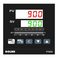
Illustrates the terminal connections for power supply, outputs, alarms, communication, and inputs for FY900/FU96.
Explains how to set the input type for the controller, including procedures and parameter settings.
Details the process of setting the Set Value (SV) for the controller, including adjustments and saving.
Describes how to perform auto-tuning to optimize PID control parameters for accurate temperature regulation.
Guides users on setting Proportional (P), Integral (I), and Derivative (D) values for PID control.
Details how to select and configure different alarm modes for monitoring and protection.
Guides users on setting specific alarm values (AL1, AL2, AL3) and their associated time settings.
Details the PV bias function used for input calibration to correct sensor deviations and improve accuracy.
Details the Heater Break Alarm (HBA) function, which monitors heater current and triggers an alarm upon disconnection.
Details the RAMP & SOAK functions for setting temperature profiles over time, including ramp rate and soak duration.
Explains the different alarm modes available (e.g., Deviation High/Low, Band, Process High/Low) and their actions.
Details the parameters required for setting up programs, including pattern selection, segments, SV, and timing.
Guides users through initial program setup, including time format, start address, repeat, and power failure protection.
Describes the process of creating a program by defining patterns and segments, including SV and timing settings.
Provides a flowchart for calibrating the output signal, ensuring accuracy for linear and other output types.
| Brand | Taie |
|---|---|
| Model | FU86 |
| Category | Controller |
| Language | English |