Do you have a question about the Taie FY series and is the answer not in the manual?
Details the terminal connections for the FY400 controller model.
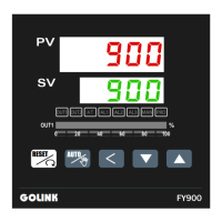
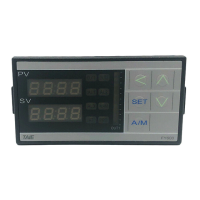
Describes the initial display and startup sequence of the controller.
Instructions on how to modify the Set Value (SV) from 0.0 to 100.0.
Guide to changing the AL1 alarm value, for example, to 5.0.
Visual representation of the controller's operational level hierarchy and navigation.
Explains how to use the lock function by setting the 'LCK' parameter.
Details parameters accessible in the User Level, including Process Value and Set Value.
| Category | Controller |
|---|---|
| Control Mode | PID, On/Off |
| Alarm | Yes |
| Communication | RS485 |
| Power Supply | 100-240VAC, 24VAC/DC |