19
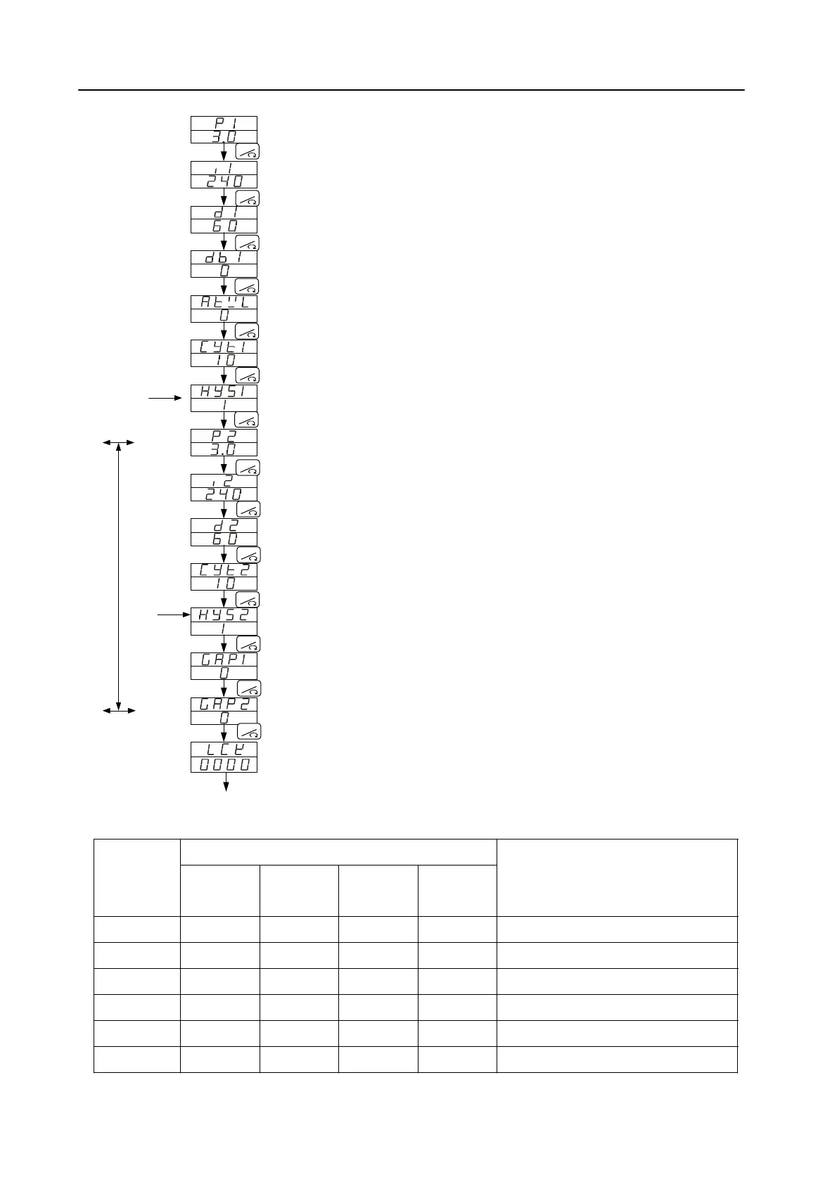
8.2.2 Description of parameters
Proportional band 1
(For
output 1)
Range
:0.0~200.0%
ON/OFF con
trol if set to 0 (0.0)
Reserved
Auto tu
ning offset value
Output 1 cycle time
Hysteresis for
output 1
ON/OFF
control
Propo
rtional band 2
(For
output 2)
Integral time 2
(For
output 2)
Derivative time 2
(For
output 2)
Output 2 Cycle time
Hysteresis for
output 2
ON/OFF
control
Con
trol gap 1
(For
output 1)
Con
trol gap 2
(For
output 2)
Fun
ction lock
Range
:0~3600 seconds
PD control if set to 0
Range
:0~900 seconds
PI
control if set to 0
Reserved
Range
:0~USPL
Range
:0~150 seconds
Re
lay output : 10
Vol
tage pulse output : 1 , mA output: 0
Rang
e:0~1000
Th
e same with P1
The same with I1
The same with D1
Th
e same with CYT1
Th
e same with HYS1
Se
t point of output 1 (Heating side)
=SV
- GAP1
=SV
+ GAP2
Return to “P1"
If P2=0.0
Display
dedivorpsi
2
t
upt
uo
fiya
l
psi
D
Integral time 1
(For o
utput 1)
Derivative time 1
(For o
utput 1)
If P1=0.0
Display
Levels entering available LCK
Level 1
(User)
Level 2
(PID)
Level 3
(Input)
Level 4
(SET)
Parameters which can be
changed
◎ ◎ ◎ ------ All parameters (default value)
◎ ◎ ------ ◎ All parameters
◎ ◎ ------ ------ All parameters except level 3
◎ ◎ ------ ------ Parameters in level 1
◎ ◎ ------ ------ “SV” and “LCK”
◎ ◎ ------ ------ Only “LCK”
RESET
RESET
RESET
RESET
RESET
RESET
RESET
RESET
RESET
RESET
RESET
RESET
RESET
RESET
0000
1111
0100
0110
0001
0101
 Loading...