Do you have a question about the Taie FY900 and is the answer not in the manual?
Important safety warnings for handling the controller and preventing electric shock.
Precautions regarding installation, wiring, and environmental conditions for safe operation.
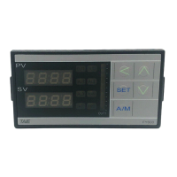
Detailed technical specifications for the FY series controllers, including voltage, power, input, output, and dimensions.
Detailed technical specifications for the FA series controllers, covering input, output, communication, and environmental ratings.
Detailed wiring diagrams and terminal assignments for the FY400 controller.
Detailed wiring diagrams and terminal assignments for the FY600 controller.
Detailed wiring diagrams and terminal assignments for the FY700 controller.
Detailed wiring diagrams and terminal assignments for the FY800 controller.
Detailed wiring diagrams and terminal assignments for the FY900 controller.
Detailed wiring diagrams and terminal assignments for the FA230 controller.
Detailed wiring diagrams and terminal assignments for the FA231 controller.
Procedure for changing the input signal type of the controller.
Guide to performing automatic PID tuning for optimal control.
Steps for manually configuring PID control parameters (P1, I1, D1).
Function to detect heater disconnection or reduced current for alarm.
How the controller manages motor-driven valves for fluid flow regulation.
How to use ramp and soak functions for temperature control sequences.
Explanation of proportional control methods and parameter settings.
Setting up communication between master and slave controllers for synchronized SV.
Compensating nonlinear input signals to achieve linear output.
Description of various alarm modes available for the controller.
Lists parameters for program pattern selection, segments, and timing.
Initial setup steps for program execution, including time format, start address, and repeat functions.
Flowchart for calibrating the 4-20mA output signal.
Step-by-step guide for calibrating CLO1 and CHO1 for output signals.
Table of error symbols, text descriptions, and corresponding solutions.
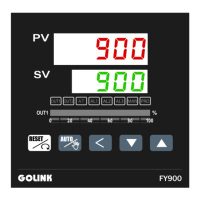
| Model | FY900 |
|---|---|
| Category | Controller |
| Display | Dual 4-digit LED |
| Input | Thermocouple, RTD, Voltage, Current |
| Output | Relay |
| Control Mode | PID, ON/OFF |
| Power Supply | 100~240VAC, 50/60Hz |