41 FY operation manual
11.2 Retransmission
Description
The retransmission function of the FY/FA series controller can provide digital values for parameters such as SV or PV etc.
Analog signals are transmitted to external devices according to the set range (EX: PLC AI module, inverter, etc.).
transmission output signal selectable: 4~20mA, 0~20mA, 0~5V, 0~10V, 1~5V, 2~10V
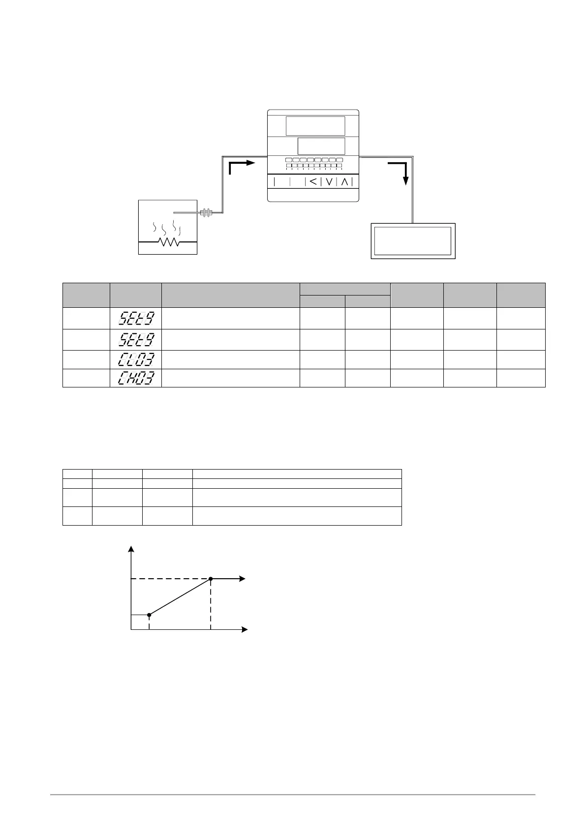
Function Diagram
Sensor
Retransmission output
Sensor input
ammeter
12.00
mA
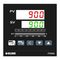
PV
SV
OUT1 %
0 20 40 60 80 100
200.0
SET A/M
TAIE
FY900
OUT1 OUT 2 AT AL1 AL2 AL3 MAN PRO
100.0
Electric
furnace
Parameter
0 : Retransmission SV disable
1 : Retransmission SV enable
0 : Retransmission PV disable
1 : Retransmission PV enable
Retransmission zero calibration
Retransmission span calibration
Examples
Assume the input range (LSPL & USPL) = -50.0~600.0 retransmit PV
When the PV value is between -50.0 and 600.0, the retransmission signal is based on the PV value,
and the linear output analog signal is presented.
When the PV is less than -50.0, the retransmission signal remains at 4mA
When the PV value is greater than 600.0, the retransmission signal remains at 20mA
Parameter setting
Retransmission signal low point calibration value
(each controller calibrate value is different)
Retransmission signal high point calibration value
(each controller calibrate value is different)
mA
4
20
Temperature
0
50.0(LSPL) 200.0(USPL)
Measured
value(PV)
Notes
1. To order TRS function, please confirm the type of retransmission output signal and retransmit signal range.
2. The user can select the source to be transmitted according to the parameter SET9.4 or SET9.3. The factory default is to
retransmit the PV.
3. Modify the parameter INP1/UNIT will reset the retransmission range.
4. CLO3 & CHO3 are the calibration parameters of the re-transmission signal. It has been calibrated before leaving the factory.
do not change this parameter value.
5. The user only needs to set SET9.4 or SET9.3, the rest of the parameters will be set & calibrated at the factory.
 Loading...