TB9300 Installation and Operation Manual Description 19
© Tait International Limited April 2024
To identify the hardware version of the PMU, refer to the compliance
label located at the rear of the module, which will contain the following
text:
PMU HW x.xx (modules sent in for repair needing a replacement
control board will have an additional label applied to the rear containing
the hardware ID).
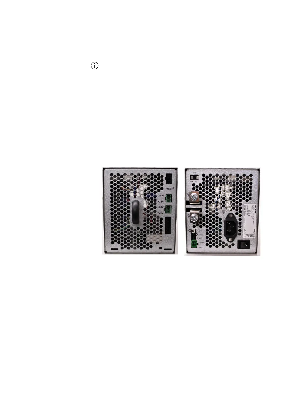
The H/W version 4 PMU (available from February 2024 initially in the AC
variant only) provides a new feature that allows a technician (via a simple
mechanical link) to select the auxiliary voltage to be 12 V, 24 V, or 48 V
(see rear view below). Note also the other hardware differences:
■ The location of the AC IEC socket has moved slightly
■ The power switch and auxiliary output socket have changed sides. The
power switch is also a different design to allow an operator to tell
immediately if the PMU is on or off.
■ The orientation of the auxiliary output socket is flipped by 180
o
a. All hardware versions of PMU can operate in any base station if they have
matching PMU firmware. Attempting to restore earlier version firmware
will not proceed if that firmware is not compatible with PMU hardware.
See the base station firmware release notes for detailed hardware com-
patibility information.
H/W version 4 PMU - front view
H/W version 4 PMU - rear view