TB9300 Installation and Operation Manual Description 21
© Tait International Limited April 2024
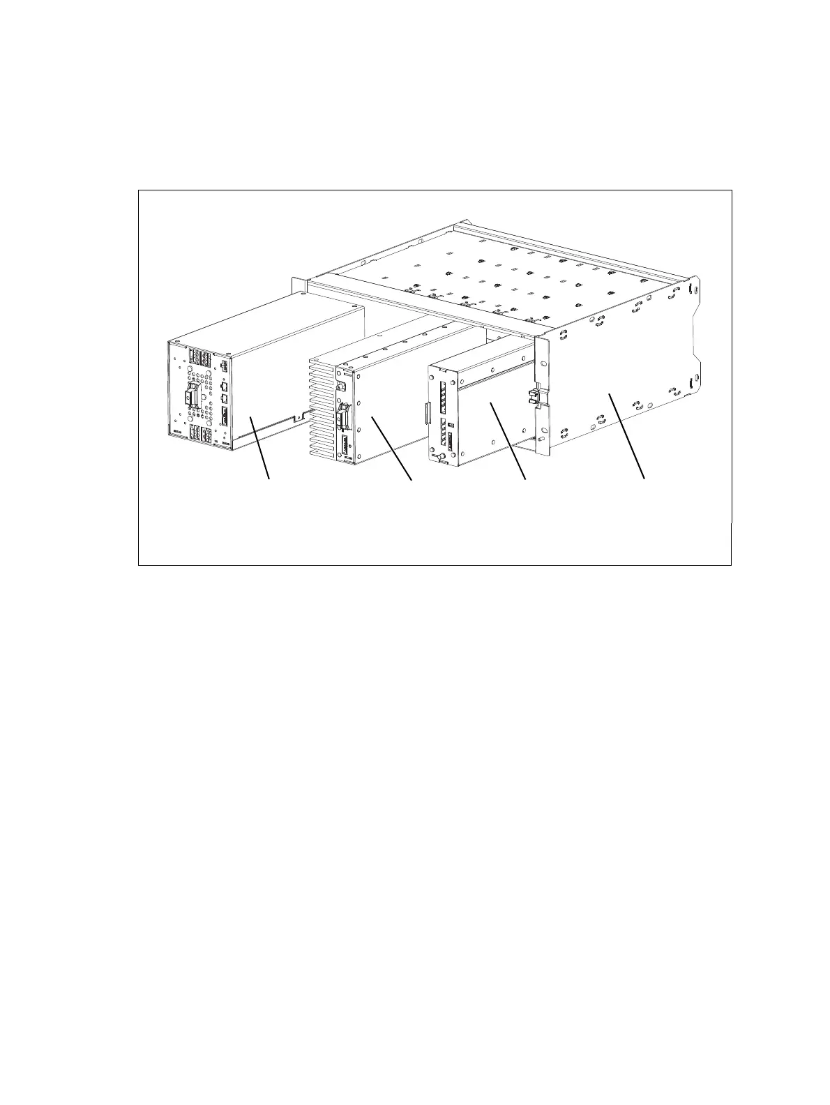
Figure 1.2 below shows the configuration for a typical single 50W base
station. The PMU again occupies slots 5 and 6, with the reciter in slot 1 and
the PA in slot 3. The single PA is mounted vertically with the heatsink
facing the center of the subrack. This positions the cooling fins directly
behind the fan.
=
Figure 1.2 Mechanical assembly - single 50W base station
b PMU d reciter
c50W PA
e subrack

 Loading...


