142 Disassembly and Re-assembly of Radio TM8100 Mobile Radio Service Manual
May 2004 © Tait Electronics Limited
Disassemble
Main-board Assembly
The third stage, if necessary, in disassembling the radio body is to
disassemble the main-board assembly.
1. Remove the rubber seal for the power connector.
2. Use a torque-driver with a 3/16-inch socket to remove the lock-
nuts for the auxiliary connector.
3. Use a torque-driver with a 14 mm long-reach socket to remove
the hexagonal nut of the RF connector. Also remove the lock
washer.
4. Use a Torx T10 screwdriver to remove the three screws securing
the copper plate on the main board to the heat-transfer block.
Access to the screws is via the holes in the
PAD TOP and PAF TOP cans
shown in Figure 6.8.
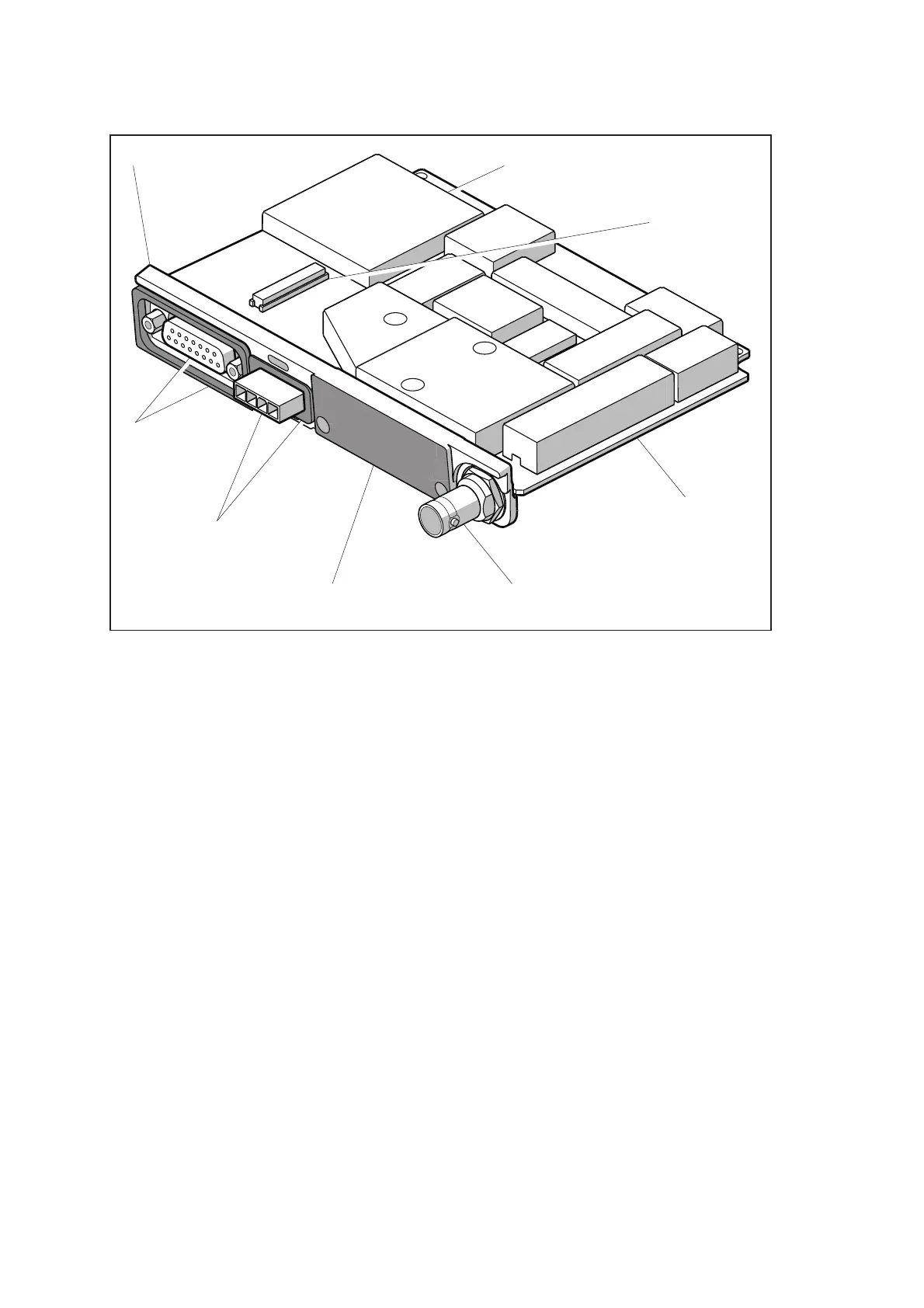
Figure 6.9 Features of the main-board assembly
AUXILIARY
CONNECTOR
AND SEAL
POWER
CONNECTOR
AND SEAL
HEAT-TRANSFER BLOCK
MAIN BOARD
DIGITAL BOARD
RF CONNECTORTHERMAL PASTE
INTERNAL OPTIONS
CONNECTOR
 Loading...


