174 Diagnosis of Faults on Main Board TM8100 Mobile Radio Service Manual
May 2004 © Tait Electronics Limited
Task 2 —
Check 3.3 V Supply
If the inputs at pin 5 and pin 7 of IC602 in the SMPS circuitry are
correct, but the radio fails to power up, then the 3.3 V DC supply needs
to be investigated.
1. First determine as follows if a fault on the digital board is affecting
the supply or preventing the radio from powering up: While
keeping the
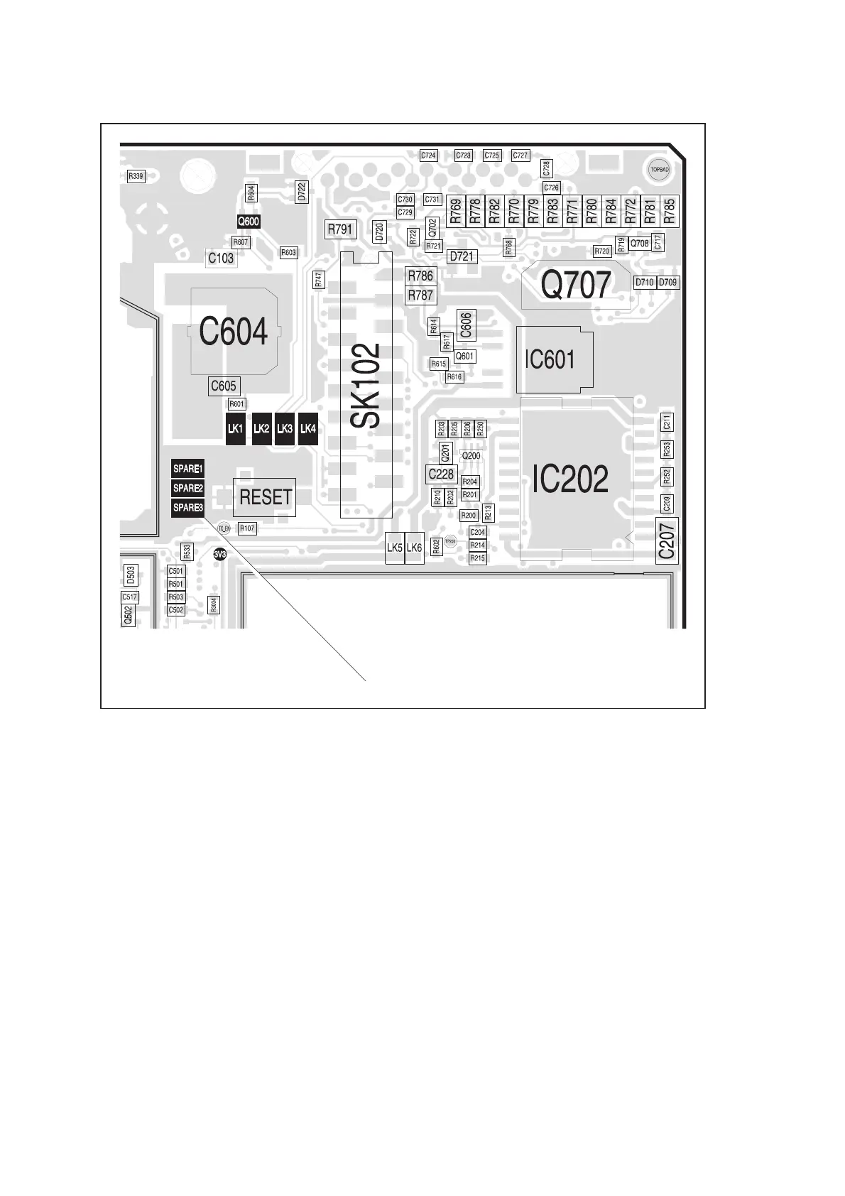
ON/OFF key depressed, measure the supply at the 3V3
test point [at 1N0/1B11] near the corner of the digital board (see
Figure 9.2). The voltage is 3.3 ± 0.1 V when there is no fault. If
the voltage is correct, the digital board is faulty; return to
Subsection 8.1 and replace the complete main-board assembly. If
the voltage is not correct, go to Step 2.
Figure 9.2 Important components of the power-supply circuitry on the top side of the main board
SPARES FOR LINKS LK1 TO LK6
CAN FOR DIGITAL BOARD
 Loading...


