TM8100 Mobile Radio Service Manual Diagnosis of Faults on Main Board 179
May 2004 © Tait Electronics Limited
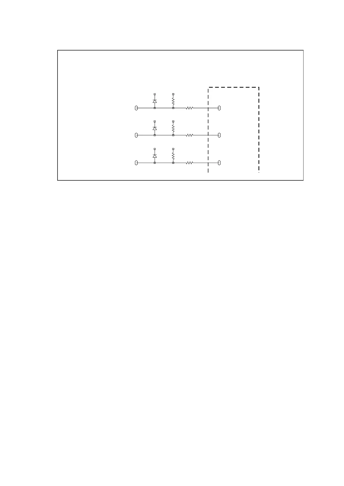
Types of Signals The connector and internal signals can be of three types:
■ output lines
■ input lines
■ bi-directional lines
For diagnosing faults in these three cases, c ar r y out Tas k 1 , Ta sk 2 or Ta s k
3 respectively. Where components need to be replaced to rectify faults,
refer to Figure 9.5 to Figure 9.7 for the locations of the components.
These figures show the three areas of the main board where the
components of the interface circuitry are situated.
Figure 9.4 Example illustrating the convention for internal and connector signals
+3V3_CL +3V3
D705
BAV70W
2
3 R723
33K
R731
1K0
IOP_GPIO7
1B2
6B4
ITF_IOP_GPO7
+3V3_CL +3V3
D706
BAV70W
1
3 R724
33K
R732
1K0
IOP_GPIO6
1B2
ITF_IOP_GPO6
+3V3_CL +3V3
D706
BAV70W
2
3 R725
33K
R733
1K0
IOP_GPIO5
1B2
ITF_IOP_GPO5
TO
INTERNAL
OPTIONS
CONNECTOR
 Loading...


