TM8100 Mobile Radio Service Manual Diagnosis of Faults on Main Board 181
May 2004 © Tait Electronics Limited
Tas k 2 —
Check Input Lines
For an input line suspected or reported to be faulty, proceed as follows:
1. For a suspect
CH ON OFF line, go to Step 4. For all other input lines
go to Step 2.
2. For the suspect line, apply a 3.3 V DC test signal to a connector
mated to the radio connector in question.
3. Check the internal signal for the line under test. If 3.3 V DC is
present, go to Step 7. If it is not, go to Step 8.
4. For the
CH ON OFF line, apply a short to ground on pin 5 of a
connector mated to the control-head connector. Check that there
is 3.9 V DC present on the
ITF ON OFF line, and that PSU ON OFF is
approximately equal to the radio’s primary supply voltage,
nominally 13.8 V DC.
5. Remove the short on the connector. Check that, with
CH ON OFF
open-circuit, both
ITF ON OFF and ITF PSU ON OFF are close to 0.0 V.
6. If the voltages given in Steps 4 and 5 are observed, go to Step 7.
If they are not, go to Step 8.
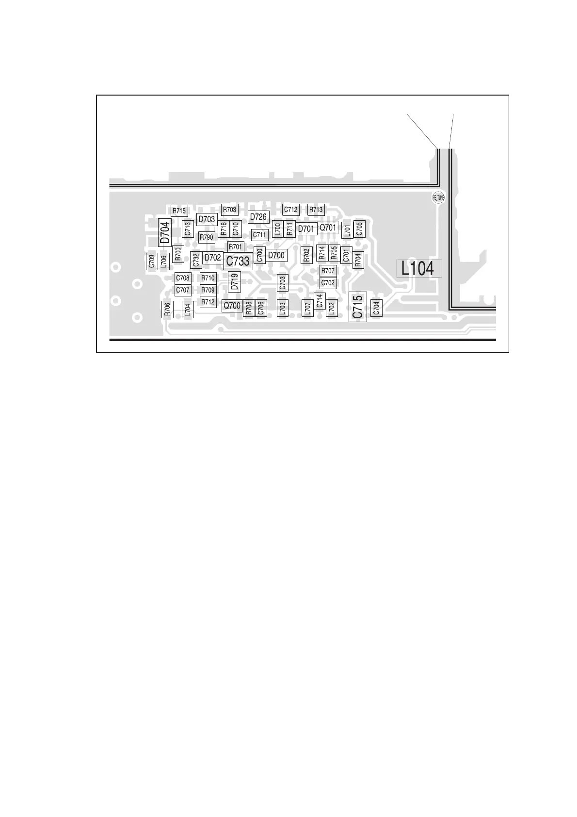
Figure 9.6 Components of the interface circuitry on the top-side of the main board near the CDC TOP
and IF TOP cans
CDC TOP CANIF TOP CAN
 Loading...


