36 General Description TM8100 Mobile Radio Service Manual
May 2004 © Tait Electronics Limited
Parts of Control
Head with UI
Figure 2.3 to Figure 2.5 illustrate the parts of a control head with UI. In
the figures each relevant part is identified by an index number. In
Table 2.1 all the index numbers are listed and the corresponding details
of these parts are given. The parts of accessory items are also identified
in the figures but are not assigned index numbers. Details of such parts
are given in the accessories manual.
Exterior of
Control Head
Figure 2.3 shows the exterior of the control head. Illustrated are the
front panel with the various keys and indicator LEDs, and the lens
covering the display. There is a rectangular aperture in the lens through
which the display is viewed. Depending on the type of control head, the
aperture is sized to fit either the one or the two characters displayed. An
identifying label distinguishes the control heads. Externally the control
heads differ only in this label and the lens. Also shown in Figure 2.3 are
the knob for the volume-control potentiometer and the access to the
microphone connector. The potentiometer and connector are mounted
on the control-head board inside the front panel.
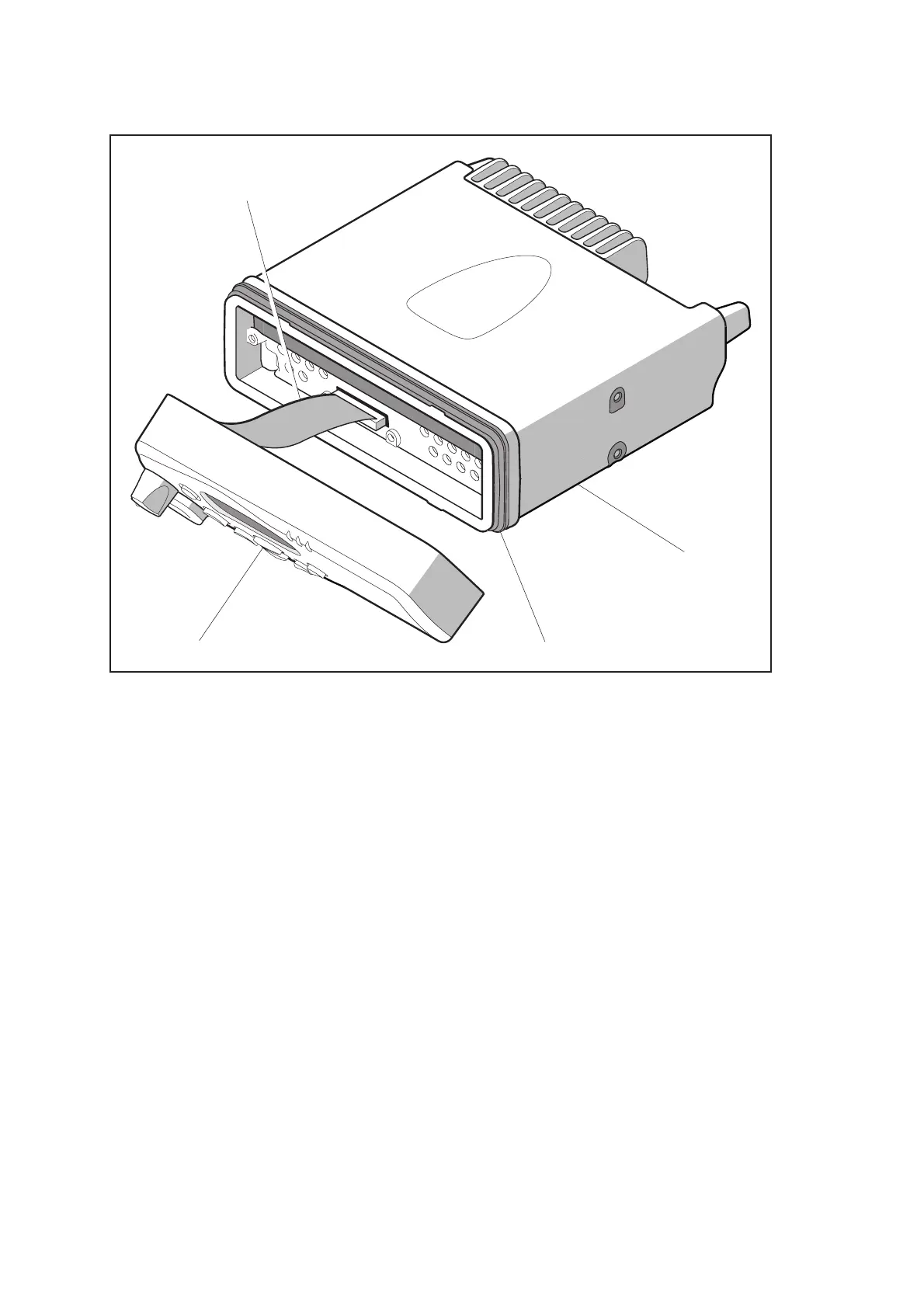
Figure 2.2 Illustration showing the control head detached from the radio body
CONTROL-HEAD LOOM
RADIO BODY
CONTROL HEAD CONTROL-HEAD SEAL
 Loading...


