TB9400/TN9275 Installation and Operation Replacing Modules 127
© Tait International Limited May 2023
3. Tighten the nut on the SMA connector to a torque of 5lbf·in
(0.6N·m).
4. Carry out the instructions in “Final Reassembly” on page 131.
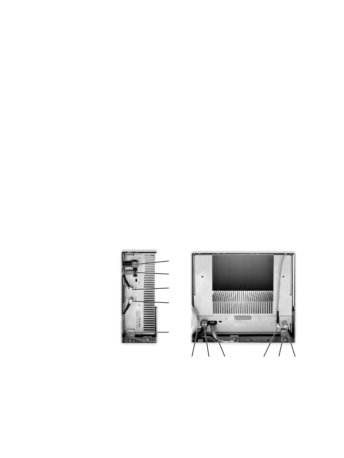
9.4 Replacing a Power Amplifier
Notice Before removing a PA, first disconnect the DC input, transmit
forward input and transmit reverse output, followed by the RF output.
After refitting the PA, reconnect the RF output first, followed by the
transmit forward input, transmit reverse output, and then the DC input.
Removal 1. If you have not already done so, carry out the instructions in “Pre-
liminary Disassembly” on page 124.
2. At the front of the PA, unplug the DC input
b, transmit forward c
and transmit reverse
d cables, and move the cables to one side.
Unplug both ends of the system control bus cable
e and remove it.
3. At the rear of the PA, unplug the RF output cable.
4. Loosen the screw securing the retaining clamp(s)
f and rotate the
clamp(s) through 90° to clear the module.
5. Slide the PA out of the subrack, taking care not to damage any of the
cables.
Refitting 1. Slide the replacement PA into the subrack and secure it with the
retaining clamp(s).
2. At the rear of the PA, connect the RF output cable.
b
e
d
c
f
be d cff
50W PA 100W PA
 Loading...