16 Tait Orca Portable (TOP) Encryption M2259-00-200-812
Encrypted Radio Programming and Service Manual Copyright TEL
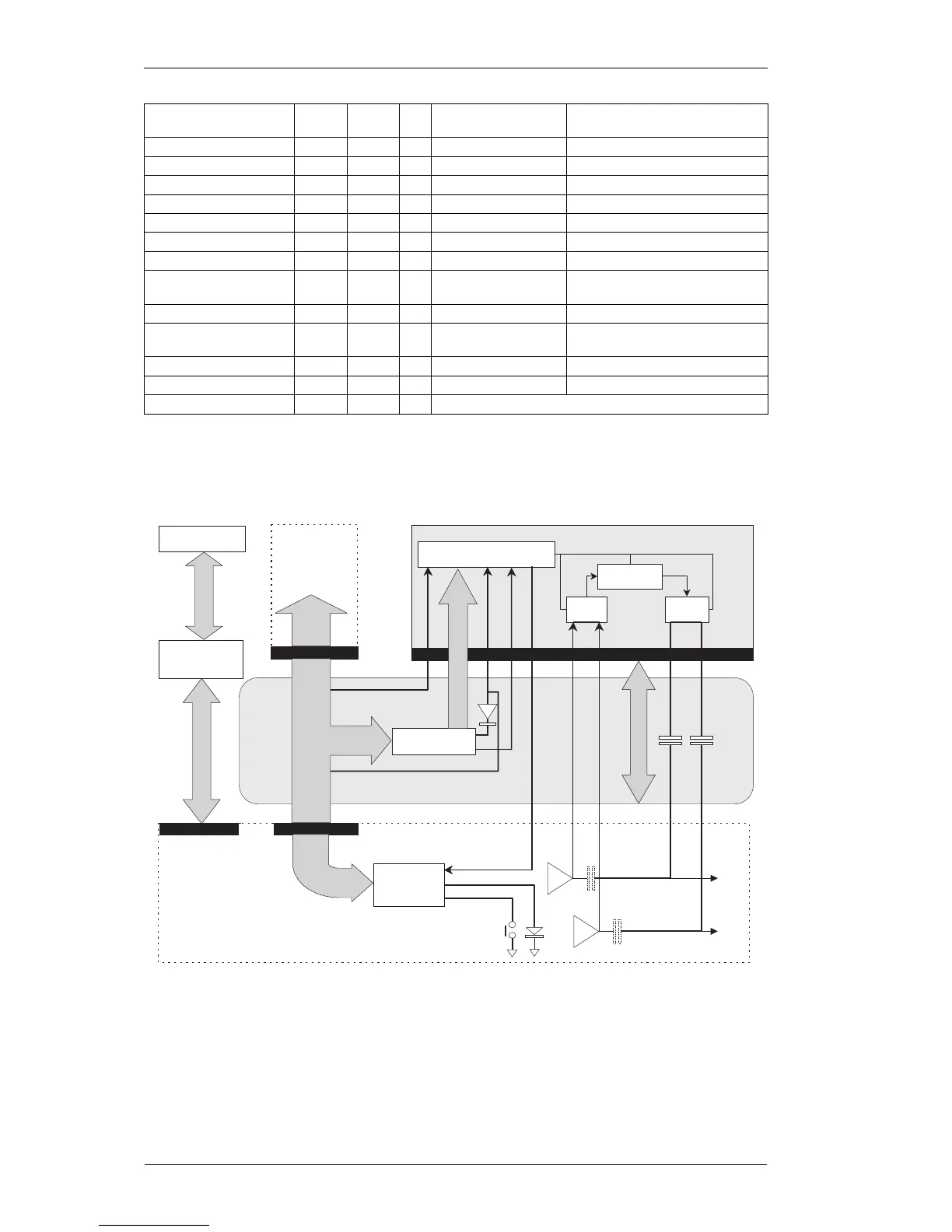
The diagram that follows shows the encryption circuit operation for both a TOP encrypted radio
and a TOP radio as a programming radio.
Note: When using a TOP radio as an OTAR programming radio, ensure encryption mode is
turned off.
An addressable latch on the radio UI board is replicated on the encryption flex and driven by the
same serial data bus. The radio micro uses four outputs of this latch to control the encryption
code select bus. Two other outputs provide the PTT and Mode drives to the module. The
remaining two pins function as normal for the UI board and are unused on the flex.
The external PTT and internal PTT are combined within the radio software to provide the PTT for
the module.
The radio LED is under normal micro control, and provides no indication of encryption status.
Data to Radio O/P D-RA 7 Hardwired module
programming O/P
If required
Mode Indicator O/P IND 8 Active high 3mA into LED
Emergency I/P EMG 9 Active Low Module pull-up to 5V
Code select 8 I/P CS8 10 Active Low Module pull-up to 5V
Code select 4 I/P CS4 11 Active Low Module pull-up to 5V
Code select 2 I/P CS2 12 Active Low Module pull-up to 5V
Code select 1 I/P CS1 13 Active Low Module pull-up to 5V
Ground Gnd 14
Transmitter to scrambler I/P TX-SC 15 AC coupled to 250Hz 200 mV p-p at 1kHz for 2/3 max
deviation
Scrambler to transmitter O/P SC-TX 16 DC coupled Approx. unity thru gain
Receiver to scrambler I/P RX-SC 17 AC coupled to 250Hz 650 mV p-p at 1kHz for 2/3 max
deviation
Scrambler to Receiver O/P SC-RX 18 DC coupled Approx. unity thru gain
Audio alert O/P AL 19 DC Coupled
Trunking delay I/P TRK 20 Provision for future
Encryption module
Flex
PCB
OTAR or Direct
Programming Cable
PTT
Sense-1
TX path
C572
to
(removed)
(removed)
modulator
Green
via DSP
Function 2
LED
C567
button
(Fn 2 button & LED normal micro use)
Rx path
to volume
Tait Orca Main PCB
control
Programming
Computer
Decode
circuit
User Interface
Board
(keypad &
display)
Micro
Controller
INTERAccessory
Encrypt /
Decrypt
Radio
Micro
Controller
Tx/Rx
switch
Tx/Rx
switch
OTAR
Programmer
RX aud, Mic, PTT
RS 232
Main-UI
PCB bus
Data bus
Code control bus
+5V, ground, busy
Mode
TX -SC
RX -SC
SC -TX
SC -RX
IND
PTT
Reset
20 way edge connector
SK1
 Loading...


