34 Page
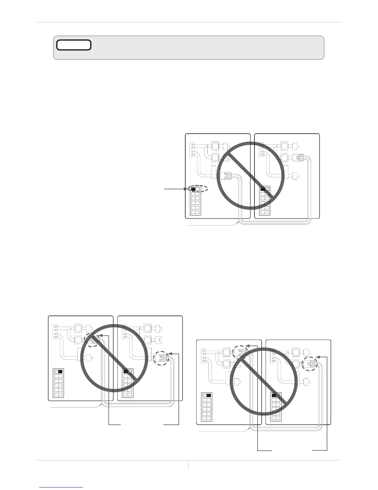
(C) Examples of incorrect settings and /or connections
CASE 1: Wrong DIPswitch setting on the "PARENT" unit
CASE 2: Wrong connections between the "PARENT" unit and the
"CHILD-1" unit
• If you connect the "1" (or "2") connector of the “PARENT” unit to the “PARENT" (or "1")
connector of the “CHILD-1” unit, the system will not work as an Easy-Link System. The units will
operate as individual units.
OR
Installaon
Installaon Manual
PARENTunit
CHILD-1 unit
Wrong
Connecons
Communicaon cable
Connectors Connectors
OFF
ON
12
34
5
6
Lower bank of
DIPswitches
Lower bank of
DIPswitches
12
3
45
6
OFF
ON
PARENT
12
PARENT
12
• Unless you change DIPswitch No. 1
of the “PARENT”unittothe“ON”
position, the system will not work
as an Easy-Link System. The units
will operate as individual units.
PARENTunit
CHILD-1 unit
WrongSeng
Communicaon cable
Connectors Connectors
OFF
ON
12
3
45
6
Lower bank of
DIPswitches
OFF
ON
12
34
5
6
Lower bank of
DIPswitches
PARENT
12
PARENT
12
PARENTunit
CHILD-1 unit
Wrong
Connecons
Communicaon cable
ConnectorsConnectors
Lower bank of
DIPswitches
12
3
4
56
OFF
ON
OFF
ON
1
2
3
45
6
Lower bank of
DIPswitches
PARENT
12
PARENT
12
• Either a temperature controller or a remote controller is required for the Easy-
Link System for ease of usage and maintenance.
NOTICE
 Loading...


