EasyManua.ls Logo

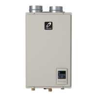
Takagi T-H3M-DV User Manual

Takagi T-H3M-DV
56 pages
To Next Page IconTo Next Page
Page #1 background imageLoading...
Page #1 background image
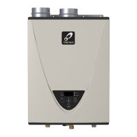
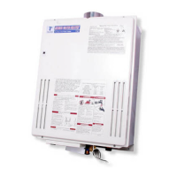
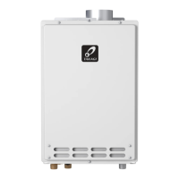
Gas Tankless Water Heater
TM
Suitable for potable water heating and space-heating
Please refer to local codes for space-heating compliance.
If you have any questions, please
call or write to:
500 Tennessee Waltz Parkway
Ashland City, TN 37015
Toll Free: 1-877-737-2840
WARNING
- Do not store or use gasoline or other
flammable vapors and liquids in the vicinity
of this or any other appliance.
- WHAT TO DO IF YOU SMELL GAS
• Do not try to light any appliance.
• Do not touch any electric switch, do not
use any phone in your building.
• Immediately call your gas supplier from
a neighbor's phone. Follow the gas
supplier's instructions.
• If you cannot reach your gas supplier, call
the fire department.
- Installation and service must be performed
by a qualified installer, service agency or the
gas supplier.
On-Demand Water Heater
Installation Manual and Owners Guide
ANSI Z21.10.3 and CSA 4.3
If the information in these
instructions is not followed
exactly, a fire or explosion may
result causing property damage,
personal injury or death.
FEATURING
• ENDLESS HOT WATER
• ON-DEMAND USAGE
• COMPACT, SPACE SAVING
• ENERGY CONSERVATION
• COMPUTERIZED SAFETY
• NO PILOT LIGHT
• Satisfies the 2012 SCAQMD Rule
1146.2 for Ultra-Low NOx
Emissions
Models
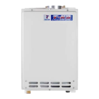
• 140 Outdoor (T-H3M-OS)
• 140 Indoor (T-H3M-DV)

Questions and Answers:

Takagi T-H3M-DV Specifications

General IconGeneral
Energy Factor0.82
Water Connection Size3/4" NPT
Gas Connection Size3/4" NPT
Vent Size4"
CategoryWater Heater
Gas TypeNatural Gas
Maximum BTU Input199, 000 BTU/hr
Voltage120V
Warranty15 Years

Summary

SPECIFICATIONS

INTRODUCTION

SAFETY GUIDELINES

SAFETY DEFINITION

Defines DANGER, WARNING, and CAUTION symbols for hazard identification.

GENERAL

Outlines general safety rules and installation considerations for the water heater.

INSTALLATION

GENERAL

Provides general guidelines and requirements for installing the water heater.

INCLUDED ACCESSORIES

CLEARANCES

VENTING INSTRUCTIONS

For the 140 Indoor (T-H3M-DV) model

Specific instructions for venting the indoor model, including material and rules.

General

General rules for venting water heaters and vent terminations.

Exhaust vent (ABS, PVC, CPVC, or polypropylene vent)

Details on using plastic vent materials, standards, and maximum lengths.

DIPswitch settings for Vent length

Guide for setting DIP switches based on vent length for different pipe sizes.

Intake and Exhaust Venting Illustrations

Visual examples of typical intake and exhaust vent installations for single pipe systems.

3 inch vent installation

Instructions for connecting 3-inch vent pipes for two-pipe and single pipe systems.

4 inch vent installation

Instructions for connecting 4-inch vent pipes for two-pipe and single pipe systems.

Examples of installation of 3 inch & 4 inch vent

Illustrates direct-vent and room-air intake installations for 3 and 4 inch venting.

Exhaust vent (Stainless steel vent)

Guidelines for using stainless steel vents, including sealing and maximum lengths.

Vent termination clearances

Specifies required clearances for vent terminals from buildings and other objects.

Exhaust and/or direct-vent sidewall terminations

Details clearances for sidewall vent terminations, including single and multiple penetrations.

For rooftop terminations

Provides clearance requirements for rooftop vent terminations.

GAS SUPPLY AND GAS PIPE SIZING

General

General precautions and information regarding gas supply and pipe sizing.

Gas connections

Instructions for making gas connections, including shutoff valves and leak testing.

Natural Gas Supply Piping

Tables detailing pipe sizing for natural gas supply based on length and capacity.

Propane (LP) Supply Piping

Tables detailing pipe sizing for propane supply based on length and capacity.

Measuring inlet gas pressure

Procedure for measuring inlet gas pressure, requiring a licensed professional.

WATER CONNECTIONS

Pressure relief valve

Requirements and installation details for the pressure relief valve.

CONDENSATE DRAIN

Condensate Drain Connections

Instructions for connecting the condensate drain, with options for neutralizer.

ELECTRICAL CONNECTIONS

TEMPERATURE REMOTE CONTROLLER

INSTALLATION

Overview of the remote controller and its installation.

Mounting and Wiring the Remote Controller

Step-by-step guide for mounting and wiring the remote controller.

How to connect the remote controller to the water heater

Detailed steps for connecting the remote controller wiring to the water heater.

HIGH-ALTITUDE INSTALLATIONS

APPLICATIONS

Space-Heating Applications

Guidance on using the water heater for space heating, including air purging.

Recirculation

Information and diagrams related to water heater recirculation systems.

Dual-purpose hot water heating

Diagrammatic layout for combined domestic and space heating applications.

INITIAL OPERATION

OPTIONAL ITEMS

OPERATING SAFETY

NORMAL OPERATION

DISPLAY OF THE CONTROLLER

Explains the different displays and indicators on the water heater controller.

GENERAL

General operational notes, including flow rates and energy saving mode.

TEMPERATURE SETTINGS

Using Remote controller

How to adjust the water temperature using the remote controller.

Temperature setting on the PCB

Method for setting temperature by adjusting DIP switches on the computer board.

ADDTIONAL FEATURES

Information mode

How to view inlet/outlet temperatures and water flow rate on the controller.

Unit conversion mode

Procedure to switch the controller display between English and S.I. units.

FLOW

FREEZE PROTECTION SYSTEM

MAINTENANCE AND SERVICE

UNIT DRAINING AND FILTER CLEANING

Step-by-step guide for draining the unit and cleaning the cold-water inlet filter.

DESCALING THE UNIT

TROUBLESHOOTING

GENERAL

General troubleshooting tips for common problems related to hot water delivery.

An ERROR code is displayed

Indicates when an error code is displayed and where to find more information.

ERROR CODES

General

Explains the self-diagnostic function and how error codes are displayed.

Fault Analysis of Error Codes

Detailed analysis and diagnosis for various error codes displayed by the unit.

COMPONENTS DIAGRAM

Case assembly

Exploded view of the indoor and outdoor unit case assemblies.

Temperature remote controller

Diagram of the temperature remote controller and its components.

Temperature controller

Diagram of the temperature controller for the indoor model.

Computer board assembly

Exploded view of the computer board assembly.

Surge box assembly

Exploded view of the surge box assembly.

Burner assembly

Exploded view of the burner assembly and its related parts.

Water Way assembly

Exploded view of the water way assemblies for indoor and outdoor models.

PARTS LIST

OUTPUT TEMPERATURE CHART

LIMITED WARRANTY

Related product manuals