21 Page
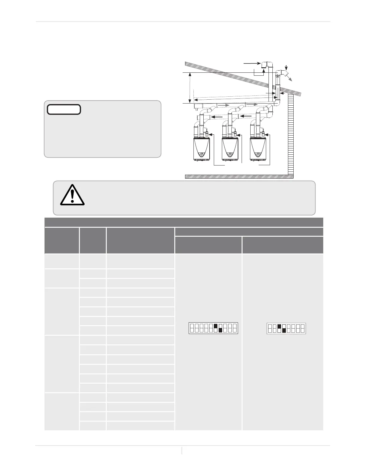
To determine the dimension of a common-venng system
Determine the vent diameter (D) and the total vent length based on the number of water
heatersinstalled.Thetotalventlength(L)consistsofthehorizontalwidth(W)andthevercal
height (H). See the table below.
• Total vent length (L)="H"+"W"
• Vent diameter="D"
WARNING
• A Non-Return Valve must be installed for each water heater. This prevents
the escape of combustion gas through non-operating appliances.
• For detailed instructions on the common-venting system, refer to the
instructions that are packaged with the vent parts or web site.
*Diameters of pipes are in accordance with Centrotherm's specifications.
**Oneelbowisequivalentto5ft(1.5m)linearlength,andthemaximumnumberofelbowsis5.
NOTICE
• Regarding the clearances
between the exhaust
termination and the
intaketerminaon,refer
to p. 22 to 24.
• Insert bird screen in
elbow terminals.
Common-venting system
Vent
Diameter*
(D)
Max.
No.of
water
heaters
Max. Vertical and
Horizontal
(Total) Vent Length** (L)
DIPswitch settings
240 Indoor (T-H3J-DV)
340 Indoor (T-H3S-DV)
540 Indoor (T-H3-DV)
(Upper bank of DIPswitches)
4 in.
(110mm)
2 25ft.(7.6m)
No.6:ON/No.7:OFF No.3 : ON / No.4: OFF
5in.
(125mm)
2 50ft.(15.2m)
3 20ft.(6.1m)
6in.
(160mm)
2 100ft.(30.5m)
3 75ft.(22.9m)
4 50ft.(15.2m
5 25ft.(7.6m)
6 20ft.(6.1m)
8in.
(200 mm)
3 100ft.(30.5m)
4 100ft.(30.5m)
5 85ft.(25.9m)
6 65ft.(19.8m)
7 50ft.(15.2m)
8 41ft.(12.5m)
10in.
(250mm)
5 100ft.(30.5m)
6 100ft.(30.5m)
7 100ft.(30.5m)
8 100ft.(30.5m)
ON
ON
Installaon
Installaon Manual
"H"
Intake
Exhaust
"D"
Elbow terminal
Elbow terminal
"W"
Non-Return Valve
 Loading...