37 Page
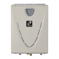
MULTI-UNIT SYSTEM
Multiple540 (T-H3)models canbecombined foraMulti-Unit System, along withthemulti-unit
controller(Part9008300005(TM-MC02)).Themulti-unitcontrollercancontrolfrom2unitsto20
units for commercial or residential applications. For a 20-unit system, the computer can modulate
betweentheusagesof13,000BTU/h(Propane)or15,000BTU/h(Naturalgas)to4.0MillionBTU/h.
An individual cut-off switch is recommended for each unit in a Multi-Unit System for the purpose
of maintenance.
Multi-Unit System connection diagram
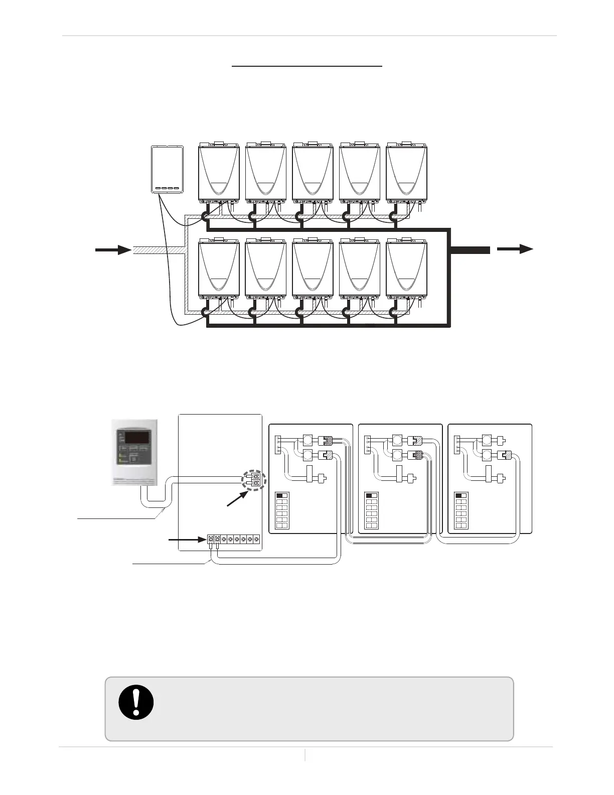
Multi-unit controller with the remote controller wiring:
• The dark squares should not need adjustment.
• Thisistheconnectiondiagrambetween540(T-H3)andmulti-unitcontrollerfor
2 to 20 water heaters. Above is a sample for 3 water heaters.
• Themulti-unitcontrollerautomaticallyallocatestheunit#(1-20)toeachwater
heater that is part of the Multi-Unit System.
• In a Multi-Unit System, connect the “[1]” connector and the “[2]” connector with
thecommunicationcable(refertop.33and34)or18gaugewirecables.The
totalcablelengthcanbeupto250ft.(76.2m)long.
OFF
ON
1
1
1
2
2
2
PARENT
PARENT
PARENT
1
2
3
4
5
6
Connectors Connectors Connectors
OFF
ON
OFF
ON
Lower bank of
DIPswitches
Lower bank of
DIPswitches
Lower bank of
DIPswitches
1
2
3
4
5
6
1
2
3
4
5
6
Communicaon cable
Remote controller cable
Unit1
Unit 2 Unit 3
Remote controller
Terminals for
water heaters
9008300005
(TM-MC02)
Remote controller
terminals
Cold IN
Hot Out
540
(T-H3)
9008300005
(TM-MC02)
Installaon
Installaon Manual
• For detailed instructions on the multi-unit controller, refer to the
instructions that are packaged with the multi-unit controller.
• When the 710 (T-M32) and 540 (T-H3) are connected together to the
multi-unit controller as a Multi-Unit System,refer to the installation
manual of the multi-unit controller for more details.
 Loading...