32 Page
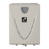
3. Tightenthetwo"Fork terminals" beneath the two "Remote controller terminal" screws on
the back of the main body. (Fig. C-1)
4. Cut out the inlet for the remote controller cable from the bottom of the main body. (Fig. C-2)
5. Placethe“Main body” back on the "Back plate", with the "Remote controller cable" running
out of the bottom inlet.
<How to connect the remote controller to the water heater>
1. Disconnectpowersupplyfromthewaterheater.
2. Takeoffthewaterheater’sfrontcover.
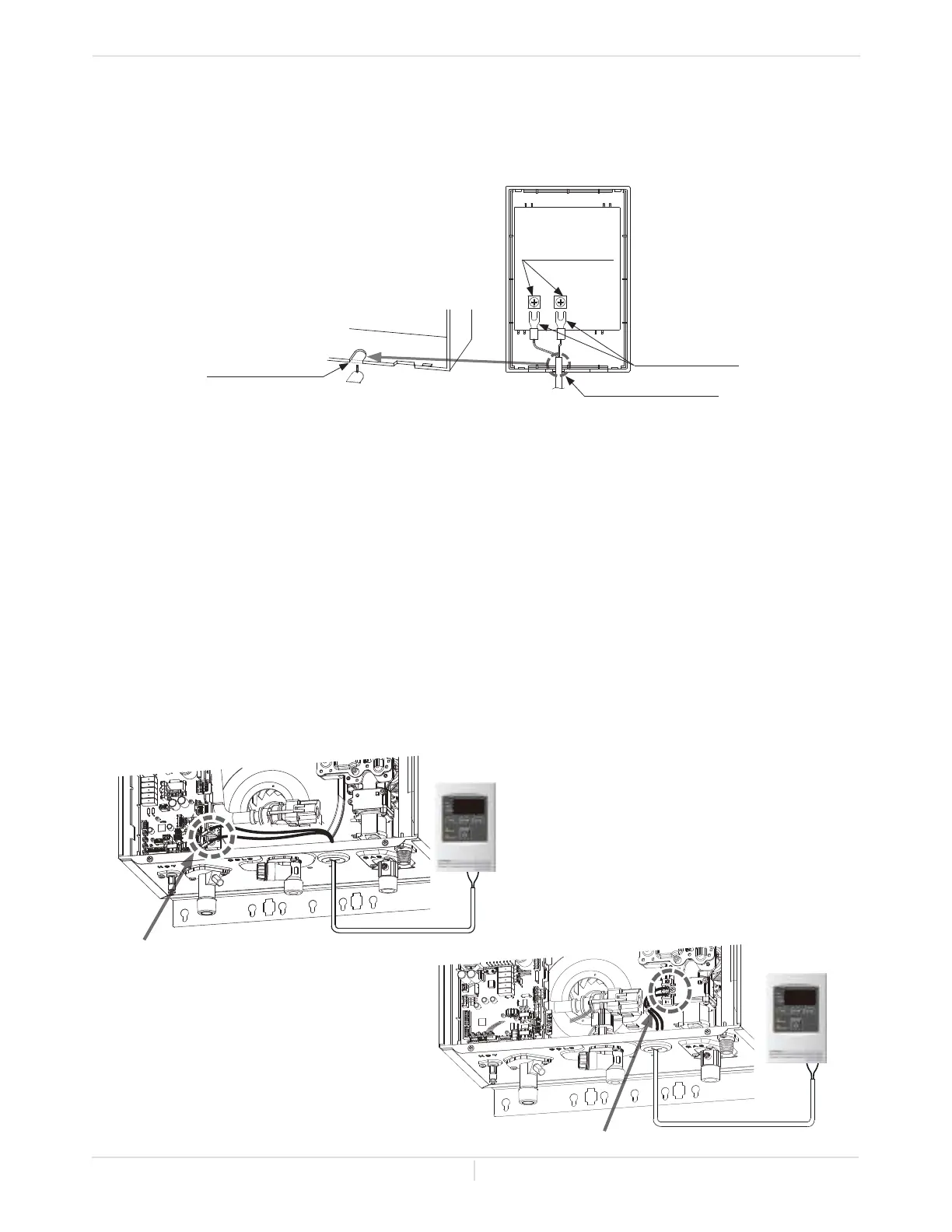
3. Locatetheremotecontrollerterminals.Seethediagramsbelow.
4. Takeoffthebackplatefromtheremotecontroller,andthenattachthetwoforkterminalsto
connector base on the backside of the remote controller with two screws. Make sure the
terminals are firmly fixed.
5. Pulltheremote’swiresthroughtheholeatthebottomofthewaterheater’scasing.
6. Properlyattachtheremote’swirestotheremotecontrollerterminalonthecomputerboard
(No polarity).
* Do NOT jump or short-circuit the wires, or computer will be damaged.
7. ReplaceFrontCoversecurely.
8. Wiresusedfortheremotecontrollerconnectionmustbe:
• Minimum 20 gauge wire (No polarity)
• Maximum400ft.(122m)long
Remote controller
terminals
Fig. C-1
Two fork terminals
Remote controller cable
Inlet for the remote
controller cable
Cut out
Fig. C-2
Installaon
Installaon Manual
540 (T-H3) model
Connect other end to these terminals
9008172005
(TM-RE40)
240 (T-H3J) and 340 (T-H3S) models
9008172005
(TM-RE40)
Connect other end to these terminals
 Loading...