- 7 -
Combustion Air Supply
The water heater location must provide enough
air for proper combustion and ventilation of the
surrounding area. See the latest edition of
ANSI Standard Z223.1 or any applicable local
codes. In general, these requirements specify
that if the unit is installed in a confined space,
there must be a permanent air supply opening.
Air Supply from Outside Building
When combustion air is supplied from outside
the building, an opening communicating
directly with the outside should have a
minimum free area of one square inch per
15,000 BTUH input of the total input rating of
water heater in the enclosed area.
Air Supply from Inside Building
When combustion air is supplied from inside
the building, an opening communicating with
the rest of the dwelling should have a minimum
free area of one square inch per 1000 BTUH
input of the total input rating of water heater in
the enclosed area. These openings should
never be less than 100 sq. in.
Minimum recommended air supply opening size
for water heater:
Combustible Air Supplied by
Mechanical fan or Make up air device.
The T-K2 water heater is equipped with a
combustible air sensor that will shut off the unit
when inadequate combustible air supply to unit
is detected.
If a mechanical fan or make up air device is
used to supply air to the water heater or utility
room, the installer should make sure it does
not create drafts which could cause nuisance
shutdowns. If a blower is necessary to provide
adequate combustion air to the water heater, a
switch or equivalent device must be wired
(interlocked) with the water heater control
circuit or other proper devices to prevent the
water heater from firing unless the blower is
operating.
VENTING INSTRUCTIONS
General
WARNING: Improper venting of this appliance
can result in excessive levels of carbon
monoxide which can result in severe personal
injury or death.
This water heater must be vented in
accordance with the section “Venting of
Equipment" of the latest edition of the Natural
Fuel Gas Code, ANSI Z223.1 and all
applicable local building codes. In Canada,
follow section 7 of the CAN/CSA B149.1
Natural Gas and Propane Installation Code.
Exhaust Vent
This is a Category III appliance and must be
vented accordingly. The vent system must be
sealed air tight. All seams and joints must be
sealed with high heat resistant silicone sealant
or UL listed aluminum adhesive tape having a
minimum temperature rating of 350ºF. For best
results, a vent system should be as short and
straight as possible.
This unit requires 4”, Category III approved,
single wall stainless steel vent pipe or any
other Category III approved, non-combustible,
corrosion-resistant material. The following are
UL listed manufacturers: ProTech Systems Inc.
(FasNSeal), Flex-L Inc., Z-Flex Inc. (Z-Vent III)
and Heat-Fab Inc. (Saf-T Vent). Follow the
vent pipe manufacturer’s instructions when
installing the vent pipe. Do not common vent
this appliance with any other vented appliance.
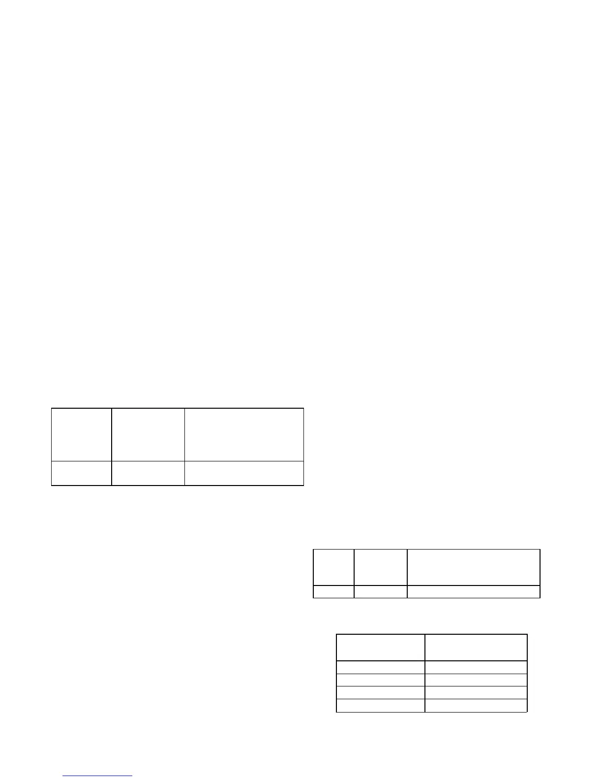
The maximum length of exhaust vent piping
must not exceed 35 ft. deducting 5 ft. for each
elbow used in the venting system. Do not use
more than 3 elbows.
Diam
eter
Max.
No. of
Elbow
Max. Vertical or
Horizontal run in
Length
4” 3 Ea. 35 ft
For each elbow added, deduct 5 ft. from
max. Vent length.
No. of Elbows Max. Vertical or
Horizontal Length
0 35 ft.
1 30 ft.
2 25 ft.
3 20 ft.
Water heater
size
When drawing
make-up air
from outside
the building
When drawing make-up
air from inside the
building (from other
rooms within)
Max. 185,000
BTU
12.3 Sq. IN 185 Sq. IN
 Loading...