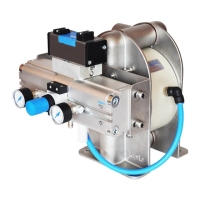
2) Manometer to read the actual pressure;
3) Needle valve to adjust the air flow (especially when operating the pump in the lower range
of performance);
4) Filter.
These components are included in Tapflo’s Air treatment system which can be ordered from
us.
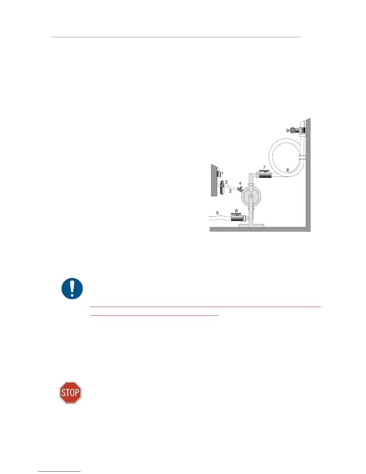
1.8. Example of installation
1) Gate valve compressed air
2) Filter and pressure regulator
3) Flexible hose
4) Needle valve
5) Flexible piping
6) Gate valve suction
7) Gate valve discharge
8) Coiled flexible piping
9) Flow gauge
1.9. Recommended installations
The Tapflo pump is flexible in the way you are able to install it.
The piping system is designed with a positive suction head. This is the best way of installation
where it is necessary to completely evacuate all liquid from the container, or where viscous
(thick) products are transferred.
NOTE! Do not exceed 0,7 bar suction pressure! Higher pressure may cause premature
diaphragm failure and irregular pump operation.
The Tapflo pump is designed to pull a high vacuum. It is able to evacuate an empty suction
pipe without any damage to the pump. The suction lift is up to 5 meters (16.4 ft.) from an
empty suction pipe and up to 8 meters (26.2 ft.) from a wetted pipe. The suction capability
depends on the pump size (see chapter 6. “Data”).
NOTE!
Even if all above safety instructions are met and complied with, there still exists a minor danger
in the event of a leakage or mechanical damage of the pump. In such case the pumped product
can emerge on sealing areas and connections.