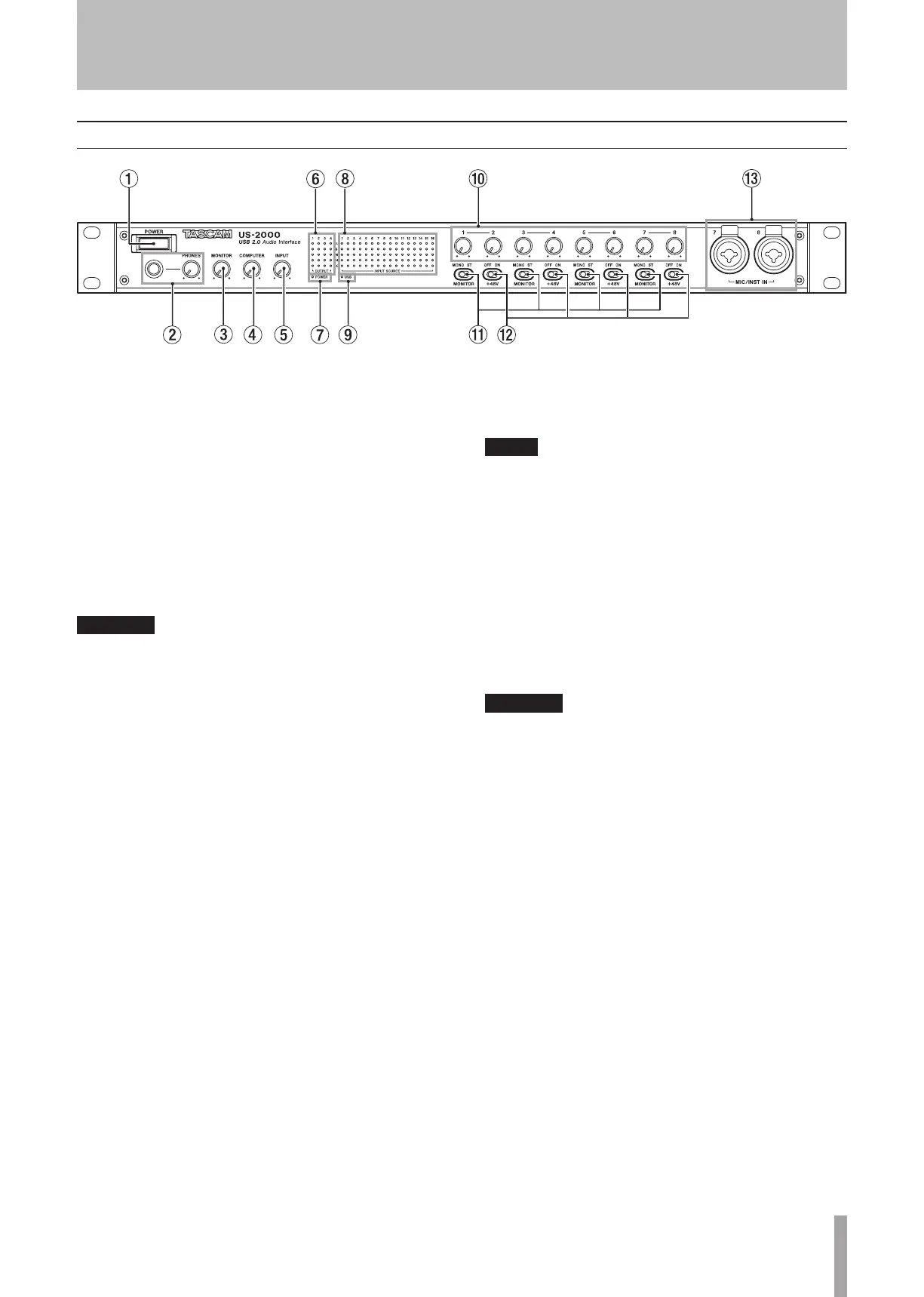
2 − Names and Functions of Parts
NOTE
Turn all the way to the left to minimize the input level
or all the way to the right to maximize the input level.
MONITOR switches
Use these switches to set whether or not adjacent inputs
1-2, 3-4, 5-6, 7-8 are monitored in mono or as stereo
pairs with odd-numbered channels (1, 3, 5, 7) on the left
and even-numbered channels (2, 4, 6, 8) on the right.
+48V switches
Use these switches to set whether or not +48 V phantom
power is provided to the mic input jacks in pairs (1-2,
3-4, 5-6, 7-8).
CAUTION
Before turning these switches ON or OFF, turn
•
the output volume down using the PHONES and
MONITOR knobs. Depending on the mic, loud noises
might be produced and damage could be caused to
equipment and people’s hearing.
Do not connect or disconnect a mic with an input
•
when its +48V switch is ON.
Turn a switch ON only when connecting a condenser
•
microphone that requires phantom power.
Do not supply phantom power to an unbalanced
•
dynamic microphone.
Some ribbon mics can be damaged by phantom
•
power. If unsure, do not supply phantom power to a
ribbon mic.
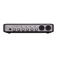
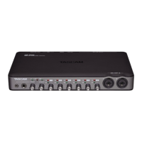
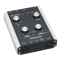
MIC/INST IN
These are analog mic/instrument inputs that combine
XLR and phone jacks. Use the XLR connectors for
balanced mic connections and the phone jacks for
electric guitars and basses, for example.
The pin assignments of the XLR jacks are 1 = GND, 2
= HOT, and 3 = COLD.
POWER switch
Use to turn the unit’s power ON and OFF.
PHONES jack and knob
Use this standard stereo phone jack to connect stereo
headphones. Use a plug adapter when connecting
headphones that have mini-plugs.
Use the PHONES knob to adjust the headphones output
level.
CAUTION
Turn the PHONES knob to the minimum volume before
connecting headphones. Failure to do so could cause
sudden loud noises and damage hearing, for example.
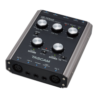
MONITOR knob
Use this to adjust the output level for MONITOR
OUTPUT L/R.
COMPUTER knob
For the signal input from the computer connected by
USB, use this to adjust the level of output from the
MONITOR OUTPUT and PHONES jacks.
INPUT knob
Use this to adjust the overall level of all the signals input
through this unit’s input jacks (mic, line and digital)
that is output from the MONITOR OUTPUT and PHONES
jacks.
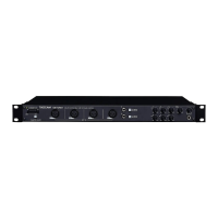
OUTPUT meters
These show output levels for the unit’s 4 outputs.
POWER indicator
This lights when the power is ON.
INPUT SOURCE meters
These show input levels for this unit’s 16 inputs.
USB indicator
This lights when the USB connection is in use.
Input gain knobs
Use these to adjust the input levels of MIC INPUTS 1–8
independently.
2 − Names and Functions of Parts
Front panel