©Copyright Task Force Tips, Inc. 2002-2018 LIX-030 January 8, 2018 Rev24
5
3.2 SPECIFICATIONS
3.2.1 MECHANICAL
CROSSFIRE Monitor SAFE-TAK 1250 Base
Weight 17 lbs 24 lbs
Storage Volume 4060 in
3
1620 in
3
L-W-H 20 x 14-1/2 x 14 20 x 9 x 9
Height Above Truck Flange 12-1/2 in NA
Height Above Truck Deck (min) 14 in NA
Height Above Ground on Base 16-1/2 in NA
Line of Reaction Force Above Ground 4 in NA
Flow Area (minimum) 8.3 in
2
8.3 in
2
Operating Temperature Range of Fluid 33 to 120° F
1 to 50° C
33 to 120° F
1 to 50° C
Storage Temperature Range -40 to 150° F
-40 to 65° C
-40 to 150° F
-40 to 65° C
Materials Used Cast Aluminum, Aluminum,
Stainless Steel
Cast Aluminum, Aluminum,
Stainless Steel
Inlets Available One Numerous Single & Double Inlets
2-1/2 in - 5 in
4.0 CROSSFIRE DEPLOYMENT
The CROSSFIRE monitor can be used on either a truck mounted fl ange or portable base. Installation on either base makes use of a
quick connect swivel joint. The use of each base and the quick connect joint is explained in the following sections.
4.1 QUICK CONNECT SWIVEL JOINT
Two pawls, actuated by the slide bar, engage in the base swivel to make the quick connect joint. A safety plunger engages in the slide
bar to prevent accidental unlocking of the slide bar when the monitor is under pressure.
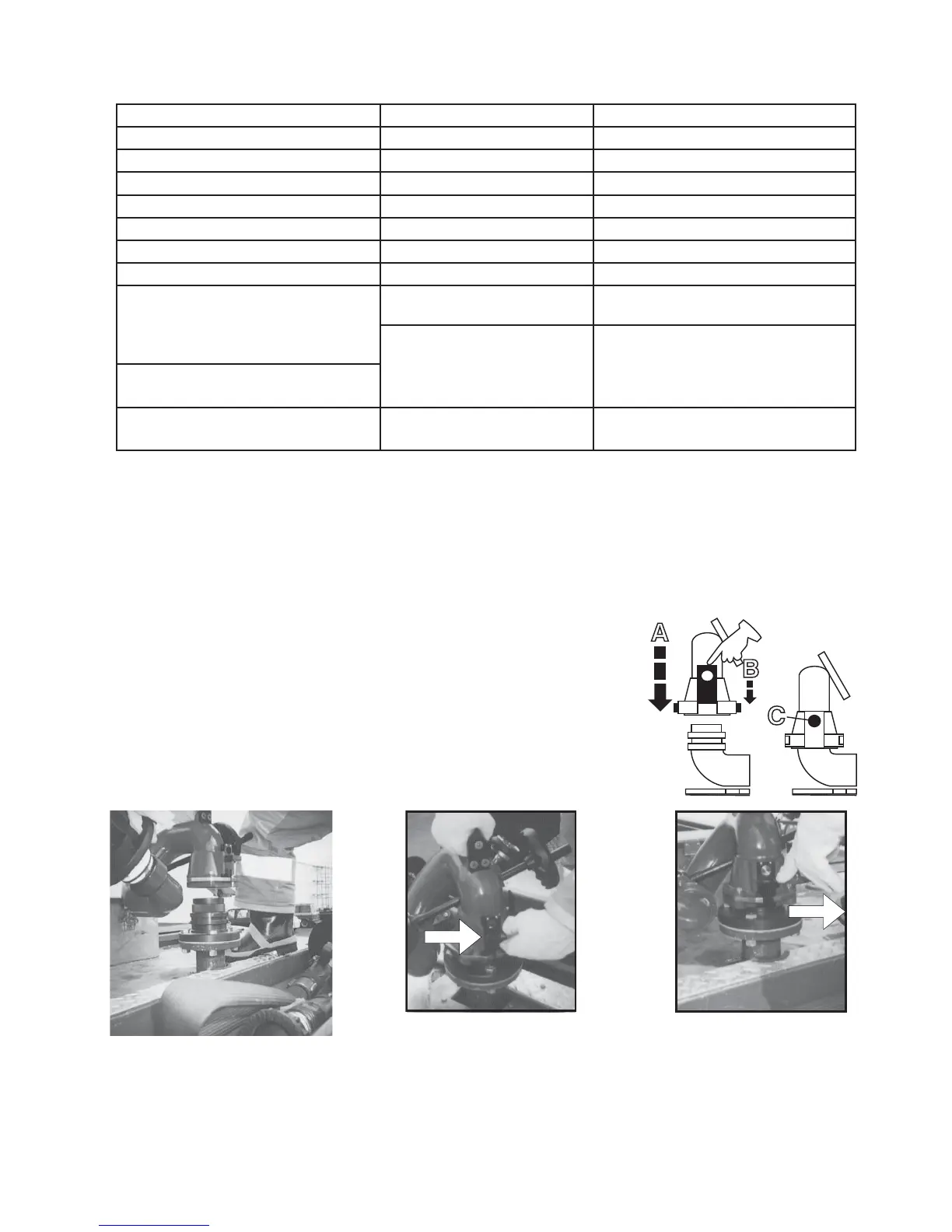
4.2 INSTALLING MONITOR ON BASE
To install the monitor on either the truck mount fl ange or portable base: Refer to fi gures
4.2.1, 4.2.2, & 4.2.3.
a) Turn elevation handwheel to make sure the elevation of the nozzle is above the 35°
safety stop. Verify that the elevation stop pin is down and engaged.
b) Make sure the slide bar is in the up position.
c) Hold the monitor by the top carrying handle, position monitor over base and slide
straight down.
d) Push the slide bar down and watch the pawls engage the groove in the base and
the safety plunger engage in the hole in the slide bar.
C
A
B
Slide bar up, safety
plunger is not engaged.
Slide bar locked, safety
plunger is engaged.
Figure 4.2.1 Figure 4.2.2 Figure 4.2.3
4.3 REMOVING MONITOR TOP FROM BASE
To remove the monitor from it’s base:
a) Stop all water fl ow.
b) Depress the safety plunger and lift the slide bar which will disengage the spring loaded pawls from the groove in the base.
c) Lift the monitor straight up off the base by the handle on top of the monitor.