©Copyright Task Force Tips, Inc. 2002-2018 LIX-030 January 8, 2018 Rev24
7
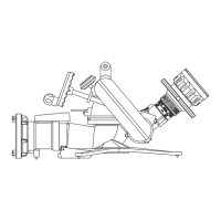
4.7 TRUCK MOUNT BASE
The CROSSFIRE monitor may be used from a truck by using a truck mount adapter. The truck mount adapter can be bolted to a
three inch riser pipe with a three inch 150 lb. ASA companion fl ange and gasket using four 5/8” bolts. It can also be screwed directly
on a 3” NPT thread. Use of pipe thread sealant is recommended. The riser must be supported to safely withstand a nozzle reaction
force of up to 900 lbs. Make sure that no interference exists between the monitor and other deck mounted equipment in any direction.
A drain valve should be provided in the riser pipe which supplies the monitor. The riser should be drained immediately after each use
during cold weather to prevent freezing and possible damage. The monitor has an automatic drain. If this drain has been disabled
(see section 3.6), the monitor must be drained by lowering the nozzle below horizontal. Installation instructions are supplied with the
truck mount base.
4.8 TRUCK MOUNTING OF THE PORTABLE BASE
In some cases a user may not have a riser directly off of the pump that can be used for mounting the monitor. In this case it may
be desirable to supply the monitor with hose lines connected to the side discharge of the pumper. In these circumstances it is
recommended that the user purchase a Deck Mount Plate, TFT part XF400-KIT, from the manufacturer. Please call 1-800-348-2686
for further information and advice concerning mounting alternatives. Installation instructions are shipped with this accessory. The
storage bracket, TFT part XF-B, for the base unit IS NOT STRONG ENOUGH to withstand the forces encountered with an operating
monitor and is not intended for this purpose.
4.9 CROSSFIRE USAGE
Because of the arched trajectory of a fi re stream, it is recommended that a spotter be used to accurately direct the stream from the
monitor. Master streams fl ows are powerful and capable of injury and damage to property. Use great care in directing the stream.
4.10 FLOWS & PRESSURES
4.10.1 STACKED TIPS
NOZZLE
DIAMETER
NOZZLE PRESSURE
50 PSI 80 PSI 100 PSI 150 PSI 175 PSI
FLOW
(GPM)
REACTION
(LBS)
FLOW
(GPM)
REACTION
(LBS)
FLOW
(GPM)
REACTION
(LBS)
FLOW
(GPM)
REACTION
(LBS)
FLOW
(GPM)
REACTION
(LBS)
1-3/8" 397 148 500 240 560 300 680 440 730 520
1-1/2" 473 177 600 280 660 350 810 520 870 620
1-3/4" 643 240 810 380 910 480 1100 712 1190 840
2" 840 314 1060 500 1190 630 — — — —
NOZZLE
DIAMETER
(MM)
NOZZLE PRESSURE
3.5 BAR 5.5 BAR 7 BAR 10 BAR 12 BAR
FLOW
(L/min)
REACTION
(KG)
FLOW
(L/min)
REACTION
(KG)
FLOW
(L/min)
REACTION
(KG)
FLOW
(L/min)
REACTION
(KG)
FLOW
(L/min)
REACTION
(KG)
35 1500 70 1900 110 2200 140 2600 200 2800 240
38 1800 80 2300 130 2500 160 3000 230 3300 280
44 2400 110 3000 170 3400 220 4100 310 4500 370
50 3100 140 3900 220 4400 280 — — — —
4.10.2 AUTOMATIC MASTER STREAM NOZZLES
Automatic nozzles maintain a constant pressure by adjusting their opening to match the available fl ow. Consult the nozzle manufacturer
for maximum fl ow and pressure ratings. In all cases, do not exceed the operating envelope.
4.10.3 STREAM STRAIGHTENERS
Stream quality, especially with smooth bore nozzles, is generally improved with a stream straightener because the water must make
many bends passing through a monitor.