©Copyright Task Force Tips, Inc. 2002-2018 LIX-030 January 8, 2018 Rev24
6
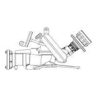
4.4 SIDE-TO-SIDE ROTATION AND ROTATION LOCK
Side-to-side rotation is accomplished by rotating the
monitor on its base. The rotational position can be
locked by moving the rotation lock lever to its down
position as shown in Figures 4.4.1 & 4.4.2. Before the
monitor is removed from the base, the rotation lock
should be manually disengaged. A small spring holds
the rotational lock in the unlocked position. When not
rotating the monitor on the base, keep the rotation
lock locked.
Figure 4.4.1
Unlocked
Figure 4.4.2
Locked
WARNING
A sliding monitor can cause injury. When used on a portable base, keep the horizontal angle
between the water stream and the anchor strap as small as possible. At large angles the base
can slide in an arc around the anchor point.
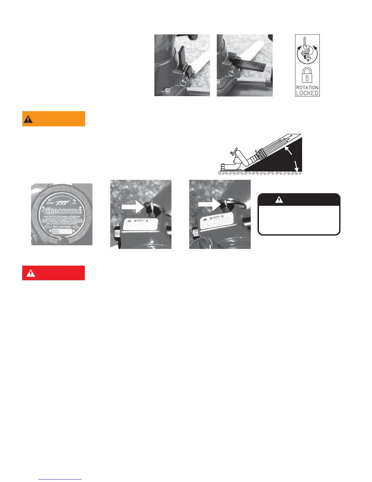
4.5 ELEVATION CONTROL AND STOP PIN
35°
The handwheel controls nozzle elevation (Figure 4.5.1). Clockwise
rotation of the wheel will raise the nozzle and counter-clockwise
rotation of the wheel will lower the nozzle. A spring loaded stop pin
limits the nozzle elevation to 35° with respect to the base.
XL090
DANGER
Operating On Portable
Base Below This Stop (pin
pulled) Is Dangerous.
Figure 4.5.1
Elevation control
Figure 4.5.2
Elevation stop pin out
Figure 4.5.3
Elevation stop pin in
DANGER
Operating on a portable base below this safety stop is DANGEROUS. Injury or death can occur if
the monitor and base slides or lifts off the ground. Do not operate on portable base below safety
stop.
When mounted on a truck base, the nozzle may be lowered below the 35° safety stop by pulling out the stop pin and rotating the
handwheel below the 35° stop. When the nozzle is raised back above 35°, the spring loaded stop pin will snap back into position
automatically limiting the elevation of the nozzle with respect to the base to 35°.
4.6 AUTOMATIC DRAIN
An automatic drain empties water from a low point in the monitor piping to prevent freezing and help empty hose lines. The valve
is designed to close automatically when pressure in the monitor exceeds approximately 5 psi and open again when the pressure
drops to that point. When the automatic drain is not desirable it may be disabled. To disable the drain valve refer to the exploded
view and follow the steps below:
1) Unscrew the drain assembly (40, 41, 42, & 43) and remove the screw and washer (42 & 43)
2) Flip over the rubber drain valve (41) so that the raised edge is against the face of the housing (40).
3) Reassemble.