PREMIER SX INSTALLATION MANUAL.
Approved Document No: GLT.MAN-101T
PAGE 8
Issue : 1.6s Authorised: GH Date: 06/11/2002
4 CONNECTING MAINS & BATTERY POWER
4.1 CONNECTING THE MAINS POWER
,1/(70$,16
6833/<
,17(51$/: ,5,1*
Figure 3: Power Supply PCB layout and Mains connection details
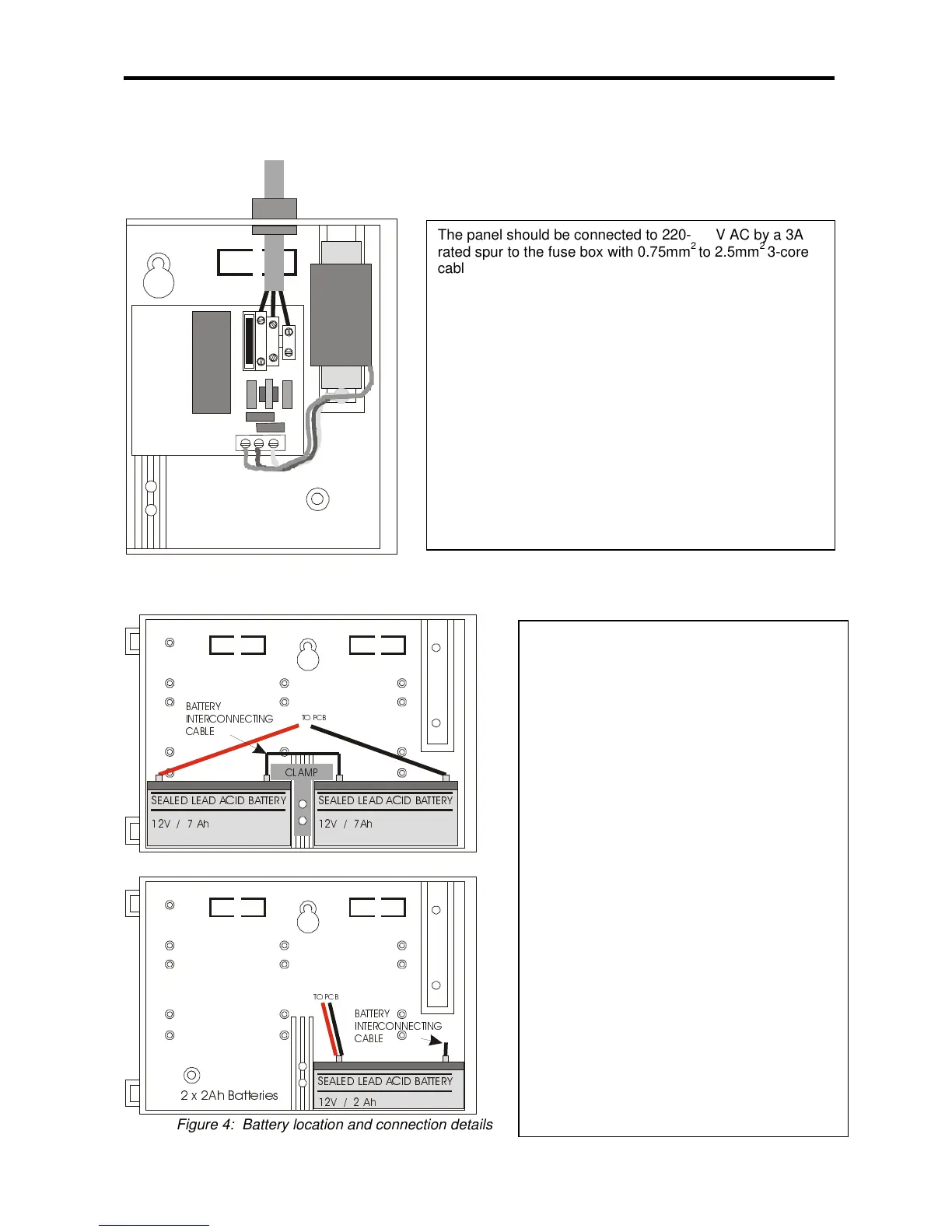
4.2 CONNECTING THE BATTERIES
6($/(' /($' $&,' %$77(5<
9$K
6($/(' /($' $&,' %$77(5<
9 $K
72 3&%
&/ $ 03
%$77(5<
,17(5&211(&7,1*
&$%/(
6($/(' /($' $&,' %$77(5<
9$K
72 3&%
[ $K %DWWHULHV
%$77(5<
,17(5&211(&7,1*
&$%/(
Figure 4: Battery location and connection details
he panel should be connected to 220-240V AC by a 3A
ated spur to the fuse box with 0.75mm
2
to 2.5mm
2
3-core
able. Nothing else should be connected to this supply
he Live, Earth and Neutral connections are marked on the
CB. The Mains is protected by a quick blow 20mm 1A
BC fuse. (Also known as HRC)
he incoming mains cable should be kept separate from
he zone cables to help minimise mains interference.
nce the mains is connected, the protective cover should
e replaced BEFORE turning on the mains power. This will
inimise the chance of electric shock from the PCB.
AKE SURE ANY SPARE ENTRY HOLES ARE
OVERED WITH THE PLASTIC GROMMETS PROVIDED
lthough there are many sizes of suitable
attery, the sizes we usually recommend are
2V 7Ah, or 12V 2Ah, and the enclosure has
een designed to hold these two sizes.
o calculate the exact requirement, use the
quation in section 10, but as a rough guide:-
/4 Zones, 24 Hr standby – 2Ah
/4 Zones, 48 Hr+ standby – 7Ah
he two batteries are wired in series.
he
+ve
of one battery is connected to the
red
he
–ve
of the other battery is connected to
he –ve of the first battery is connected to the
ve of the second battery using the link wire
hen fitting the batteries, take care not to
amage the temperature monitoring
hermistors. See figure 4a overleaf.