PREMIER SX INSTALLATION MANUAL.
Approved Document No: GLT.MAN-101T
PAGE 15
Issue : 1.6s Authorised: GH Date: 06/11/2002
11. PCB TERMINATION CONNECTIONS.
)6
%$77(5<
$
)6
61'
P$
)6
(Q 683
$
)6
&+$5*(5
$
)6
61'
P$
/,9( 1(87 ($57+
5$/
0$,16 72 75$16)250(5 35,0$5<
0$,16 )86(
$ +5& &(5$0,&
&211
&211
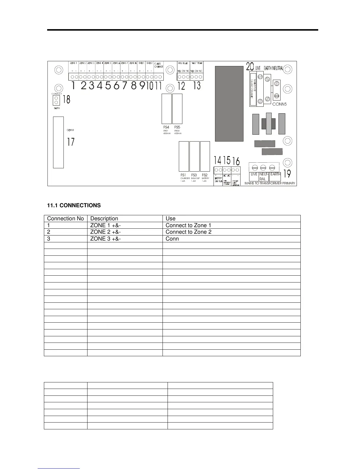
11.1 CONNECTIONS
Connection No Description Use
1 ZONE 1 +&- Connect to Zone 1
2 ZONE 2 +&- Connect to Zone 2
3 ZONE 3 +&- Connect to Zone 3
4 ZONE 4 +&- Connect to Zone 4
5 ZONE 5 +&- Connect to Zone 5
6 ZONE 6 +&- Connect to Zone 6
7 ZONE 7 +&- Connect to Zone 7
8 ZONE 8 +&- Connect to Zone 8
9 SND 1 +&- Connect to sounder circuit 1 (sirens/bells)
10 SND 2 +&- Connect to sounder circuit 2 (sirens/bells)
11 CLASS CHANGE Join terminals to activate sounders
12 FIRE RELAY NO/CM/NC Activates on fire (including test mode)
13 FAULT RELAY NO/CM/NC Normally powered ie NO is closed with no fault
14 BATTERY + & - Connect 2 x 12V SLA batteries in SERIES (ie 24V)
15 AC AC Connected to transformer secondary (30VAC)
16 EN54 supply - & + NOT CONNECTED IN STAND ALONE PANEL.
17 CONN 1 20 way ribbon cable to display PCB
18 CONN 27 EARTH connection to display PCB & SCREEN TAG
19 CONN 26 Filtered mains to transformer
20 CONN 5 MAINS TERMINAL BLOCK
11.2 FUSES
FUSE NO DESCRIPTION RATING
FS1 Charger Fuse 1.6A time delay 5 x 20mm glass
FS2 Battery Fuse 1.6A time delay 5 x 20mm glass
FS3 EN54 SUPPLY (NOT USED) 1.6A time delay 5 x 20mm glass
FS4 Sounder circuit 1 400mA time delay 5 x 20mm glass
FS5 Sounder circuit 2 400mA time delay 5 x 20mm glass
INLET FUSE Mains Protection Fuse 1A Quick Blow HBC 5 x 20mm ceramic