PREMIER SX INSTALLATION MANUAL.
Approved Document No: GLT.MAN-101T
PAGE 10
Issue : 1.6s Authorised: GH Date: 06/11/2002
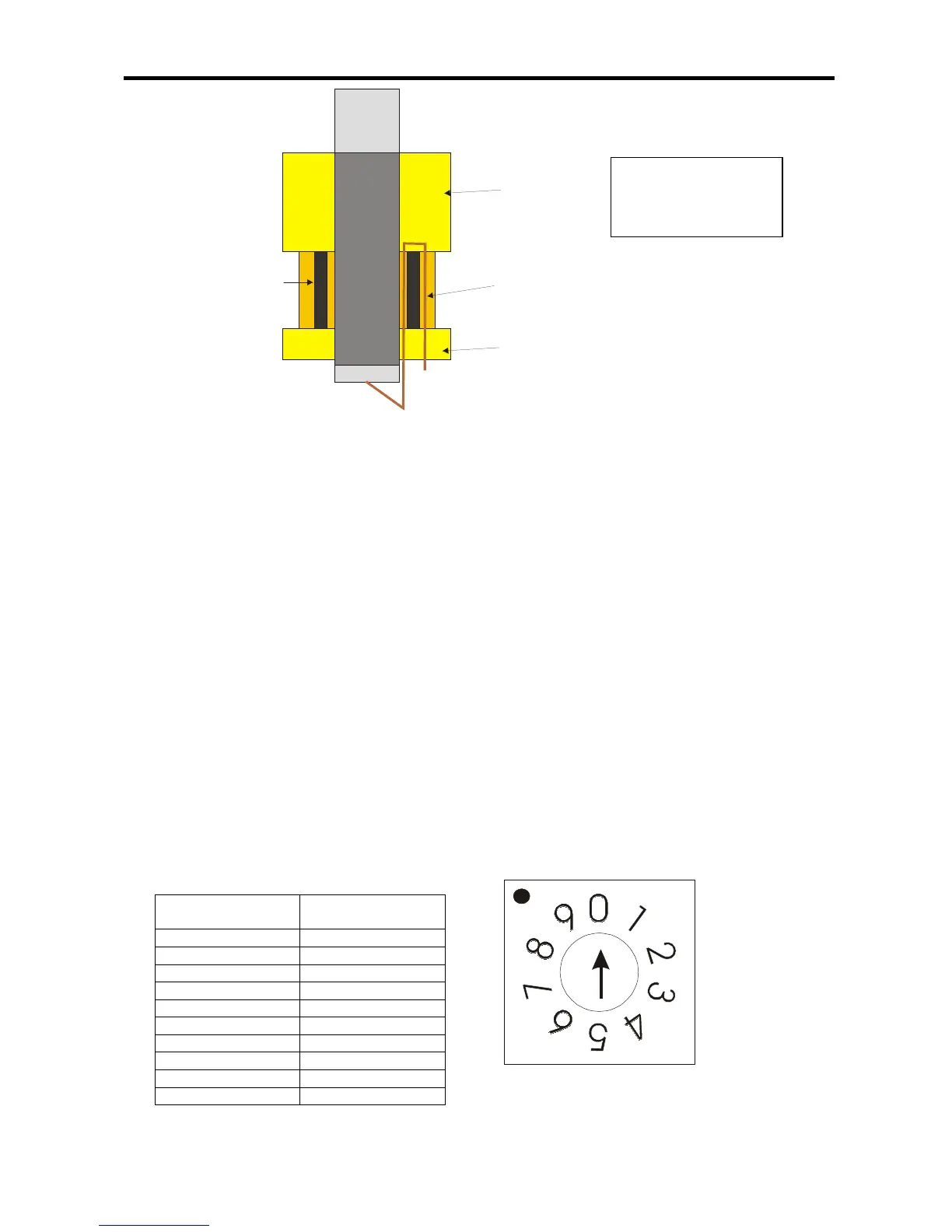
*ODQG
1XW
5XEEHU6HDO
6FUHHQFDEOH
Figure 6a: Expanded view of brass cable gland.
5.2 CONNECTING THE AUXILIARY INPUTS AND OUTPUTS
Incoming auxiliary input and output cables should be connected to the relevant connector block
terminals on the Main Control PCB. If screened cables have been used, all screens should be
terminated as per figure 6.
For a full description of the inputs and outputs available on the Premier SX range of Fire Panels,
including typical wiring diagrams please refer to pages 5 & 6.
6. SOUNDER ACTIVATION DELAY
6.1 DECIDING TO USE A DELAY
A delay of up to nine minutes from the Fire Alarm Panel being triggered, to its Alarm sounder outputs
being activated, can be programmed into the panel by the Engineer. This is a particularly useful
feature for schools, nightclubs and other public places where the nuisance and panic caused by a
false alarm must be avoided. It should be noted that the delay period will apply to ALL zones.
When an Alarm occurs on any zone, it is processed as normal. However, the activation of the
sounders is postponed until the delay period has expired, thus allowing the cause of the Alarm to be
investigated by the User. If the alarm is false the alarm can be cancelled.
6.2 TO SET DELAY
Open the panel door using Alan Key provided and set switch 7 (
SW7
) using a terminal screw driver to
the delay required
SW7 Setting External sounder
delay in minutes
0 No delay
1 1 minute
2 2 minutes
3 3 minutes
4 4 minutes
5 5 minutes
6 6 minutes
7 7 minutes
8 8 minutes
9 9 minutes