15
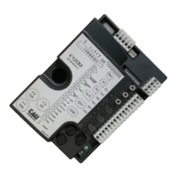
K892M
ENGLISH
CONTROL CARD FOR 1 OR 2 230V AC SINGLE-PHASE MOTORS FOR OVERHEAD DOORS
• MICROPROCESSOR-CONTROLLED LOGIC
• INPUT STATUS LED’S
• LINE INPUT FUSE
• BUILT-IN FLASHING LIGHT CIRCUIT
• 433.92 MHz 2 CHANNEL BUILT-IN RADIO RECEIVER (CH)
• INCORPORATED ELECTRONIC TORQUE LIMITER
• ELECTRONIC PEAK LOAD CONTROL
• CONTROL OF THE SENSITIVE EDGE according to the EN 954-1 standard
ATTENTION:
- do not use single cables (with one single wire), ex. telephone cables, in order to avoid
breakdowns of the line and false contacts.
- do not re-use old pre-existing cables.
TESTING
When you have completed the connection:
• All the green LEDs must be on (each of them corresponds to a Normally Closed input). The go off
only when the controls to which they are associated are operated.
• The red DL5 LED must be off (corresponding to the Normally Open OPEN/CLOSE input). It only
comes on when it is activated by the control to which it is associated.
• The red DL7 LED must be on (giving indications during the programming of the radio control de-
vice).
TECHNICAL CHARACTERISTICS
Power input to board 230V AC - 50 Hz
Max motors nominal power 400 W
Fast acting fuse for protection of auxiliary circuits 24 V dc
(F1 - 5x20)
F 500 mA
Input voltage of motor circuits 230V AC
Input voltage of auxiliary circuits 24V AC
Fast acting fuse for protection of input power supply 230 Vac
(F2 - 5x20) F 6,3 A
Working temperature -20°C ÷ +55°C
DIAGNOSTICS LED
DL1 SENSITIVE EDGE green LED signal
DL2 OPEN LIMIT SWITCH green LED signal
DL3 CLOSE LIMIT SWITCH green LED signal
DL4 External input STOP green LED signal (terminal 17)
DL5 OPEN/CLOSE button red LED signal
DL6 PRESSURE-SENSITIVE EDGE green LED signal
DL7 RECEIVER PROGRAMMING INFORMATION and ERRORS red LED signal
DL8 Integrated push button panel Stop green LED signal
TERMINAL BOARD CONNECTIONS
Terminals Function Description
1 - 2 POWER SUPPLY Power input 230Vac, 50Hz, single-phase; 1 = Phase; 2 = Neutral;
3 - 4
COURTESY LIGHT
Output for auxiliary courtesy light 230 Vac;
5 - 6 FLASHING LIGHT Flashing light output 230 Vac 20 W max.
7 - 8
AERIAL
433,92 MHz built-in RX aerial input; 7 = Earth 8 = Signal;
9 - 10 2
nd
RADIO CH
2
nd
radio channel output;
Warning: to connect other devices to the 2nd Radio Channel
(area lighting, pumps, etc.), use an additional auxiliary relay.