6-4
OPERATING PROCEDURES
Model 736
Operating Procedures
6
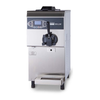
10. Position the draw handle with the adjustment screw
facing down. Slide the ball of the draw handle into the
slot of the draw valve. Secure the draw handle to the
door using the pivot pin. Place the handle pin O-ring
in the groove at the end of the pin.
Figure 6-14
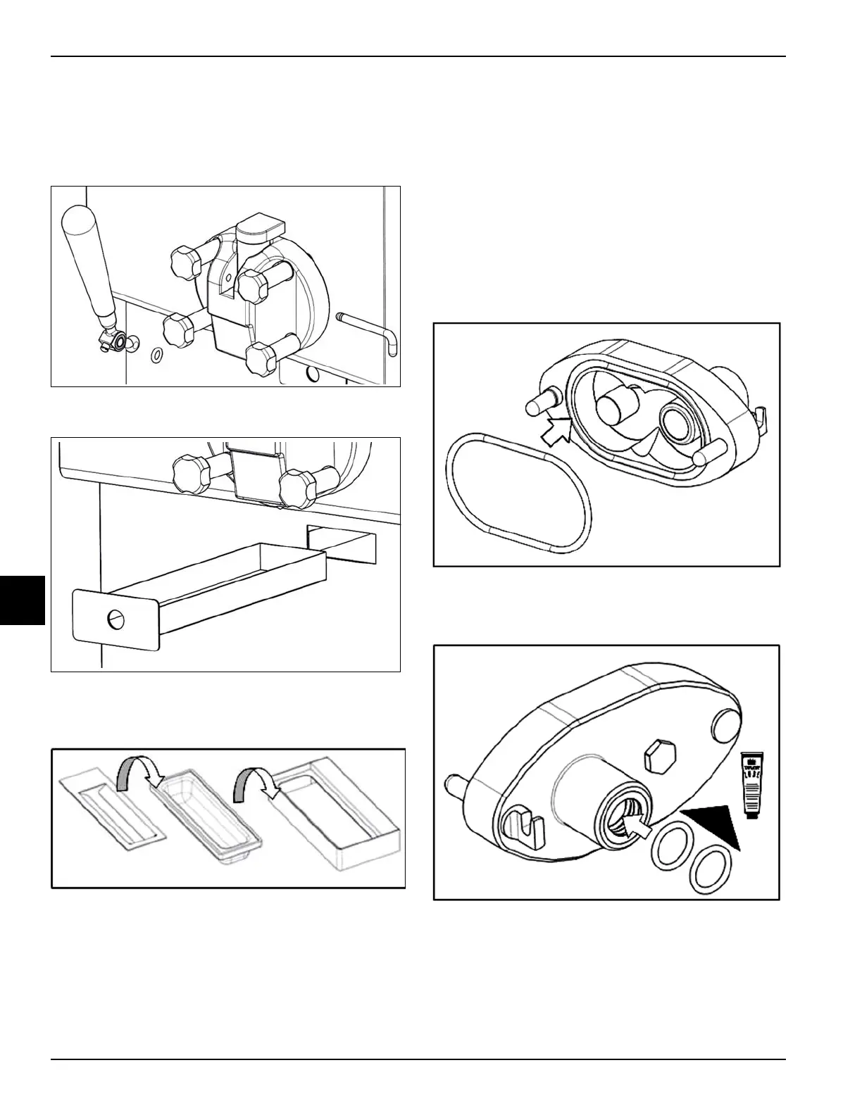
11. Slide the drip pan into the hole in the front panel.
Figure 6-15
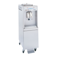
12. Install the front drip tray bracket, rubber drip tray, and
splash shield under the door spout.
Figure 6-16
Mix Pump Assembly
1. Inspect the rubber and plastic pump parts. The
O-rings must be in 100% good condition for the pump
and entire machine to operate properly. They cannot
properly serve their intended function if nicks, cuts, or
holes in the material are present.
Inspect the plastic pump parts for cracks, wear, and
delamination of plastic.
Replace any worn, damaged, or inoperable parts
immediately.
2. Place the pump body O-ring in the groove.
Figure 6-17
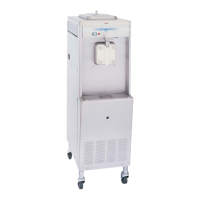
3. Place the two pump O-rings into the groove on the
back of the pump body and lubricate them.
Figure 6-18