9
Models 150, 152, 162, 168
Introduction
Installation Instructions
Air Cooled Units
Air cooled units require a minimum of 6” (15.2 cm) of
clearanceonallsides of the freezer . Failure to allow for
adequate clearance can reduce the refrigeration
capacity of the freezer and possibly cause damage to
the compressor.
Water Cooled Units
An adequate cold water supply with a hand shut-off
should be provided.
Step 1
Flush all water lines.
Step 2
Connect the water supply line to the inlet (water in)
connection.
Note: If local codes permit, use flexible water lines.
Step 3
Install the drain line into an open trap drain so that the
water flow can be observed.
IMPORT ANT: Do not install a shut-off valve on the
drain line.
Note: Drain water should be warm during normal
operation.
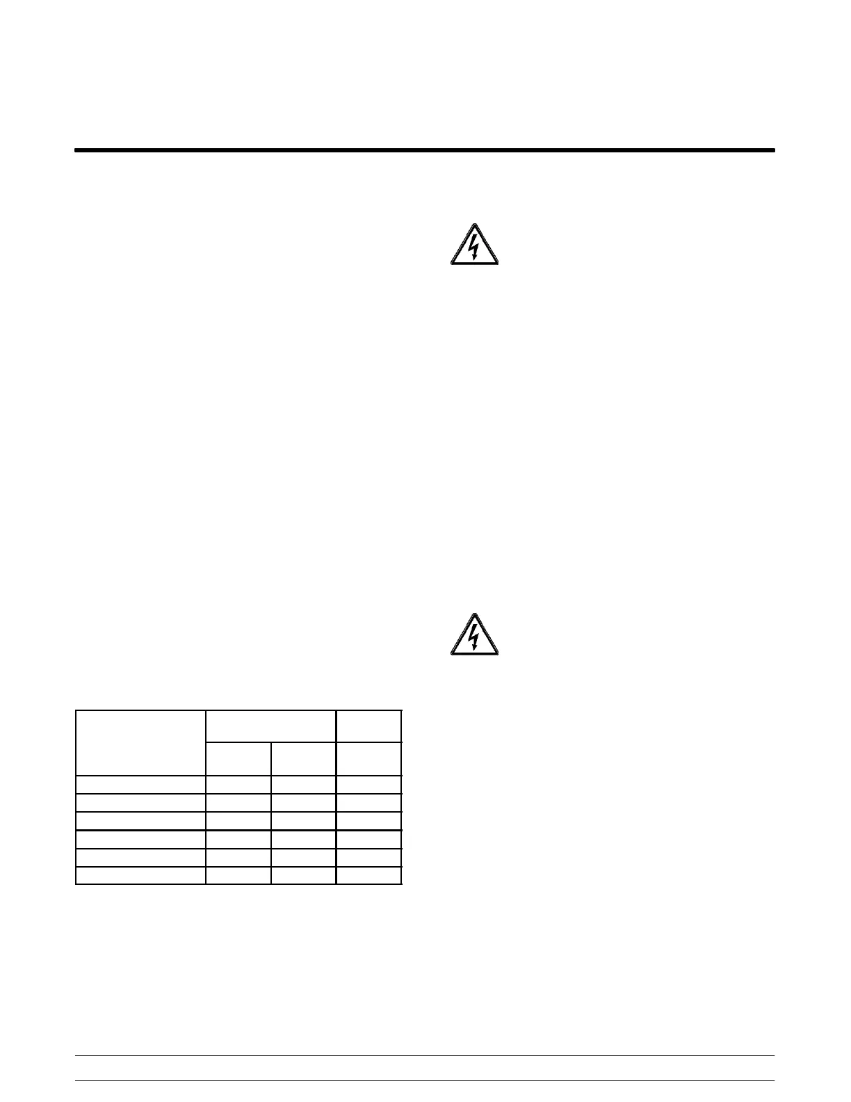
Refrigeratio n
R502
404A /
HP62
o
e
Air
Cooled
Water
Cooled
Air
Cooled
150 Temp. Control 40
150 TQC 34 18
152 Temp. Control 40
152 TQC 34
162 TQC 34 23 18
168 TQC 34 20 18
Separate Hopper Refrigeration
Single Hopper: R12 = 7 oz., 134A = 4.5 oz.
Double Hopper: R12 = 8 oz., 134A = 4.5 oz.
Note: Refrigerant charges are subject to change.
Always refer to the freezer data plate.
Beater Rotation
TURN THE POWER SWITCH OFF! Failure
to follow this instruction may result in electrocution.
Step 1
Remove the door assembly and the beater. Press the
push button switch on the underside of the control
channel. This switch is a latching relay system and will
only drop out if thepower is disconnected, or if abeater
motor overload occurs.
Step 2
Place the power switch in the “W ASH” position. This
activates the beater motor only.
Step 3
Look into the freezing cylinder. The female hex drive
coupling should be turning clockwise.
Step 4
If rotation is not correct, follow the directions on the
beater motor to reverse the rotation.
REMEMBER TO DISCONNECT ALL
POWER TO THE FREEZER! Failure to follow this
instruction may result in electrocution.
Electrical Connections
Each freezer requires one dedicated power supply.
Check the data label on the freezer for fuse, circuit
ampacity and electrical specifications. Refer to the
wiring diagram, provided inside the control box, for
proper power connections.
This equipment is intended to be installed in
accordance with the National Electric Code (NEC),
NFPA 70. The purpose of this code is the practical
safeguarding of persons and property from hazards
arising from the use of electricity. This code contains
provisions considered necessary for safety.
Compliance therewith and proper maintenance will
result in an installation essentially free from hazard.
 Loading...


