OPERATING PROCEDURES
6-7
Models 358 and 359
Operating Procedures
6
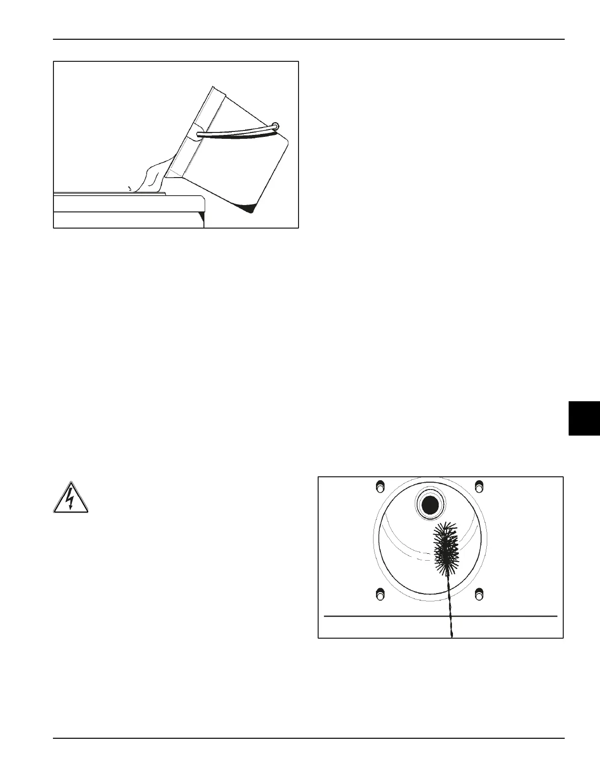
Figure 6-23
3. While the solution is flowing into the freezing cylinder,
brush-clean the mix hopper, mix-level sensing probe,
and mix inlet hole.
4. Place the power switch in the Wash position. This will
cause the cleaning solution in the freezing cylinder to
be agitated.
5. Place an empty pail beneath the door spout and raise
the draw handle. Draw off all the cleaning solution.
When the solution stops flowing from the door spout,
lower the draw handle and place the power switch in
the OFF position.
6. Repeat steps 1 through 5 for the other side of the
freezer on Model 359.
Disassembly
WARNING! Make sure the power switch is in
the OFF position before installing/removing any parts.
Failure to follow this instruction may result in severe
personal injury or electrocution.
Remove the freezer door, beater, scraper blades, and
driveshaft from the freezing cylinder. Take them to the
sink for cleaning.
1. Repeat for the other side of the freezer on Model
359.
2. Remove the front drip tray and the splash shield.
Brush-Cleaning
1. Prepare a sink with an approved cleaning solution
(example: Kay-5
®
or Stera-Sheen
®
). Use warm water
and follow the manufacturer's specifications.
Important! Follow label directions, since too strong
of a solution can cause parts damage, while too mild
of a solution will not provide adequate cleaning.
Make sure all brushes provided with the freezer are
available for brush-cleaning.
2. Remove the seal(s) from the driveshaft(s).
3. From the freezer door(s), remove:
•Gasket(s)
• Front bearing(s)
• Draw valve(s)
Remove all O-rings.
Note: To remove O-rings, use a single-service towel
to grasp the O-ring. Apply pressure upward until the
O-ring pops out of its groove. With the other hand,
push the top of the O-ring forward. It will roll out of the
groove and can be easily removed. If there is more
than one O-ring to be removed, always remove the
rear O-ring first. This will allow the O-ring to slide
over the forward rings without falling into the open
grooves.
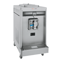
4. Return to the freezer with a small amount of cleaning
solution. With the black bristle brush, brush-clean the
rear shell bearing(s) at the back of the freezing
cylinder(s).
Figure 6-24