Section 6
6-1
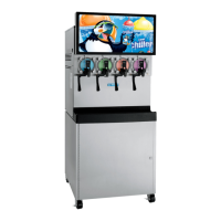
Model C302
Operating Procedures
6
Operating Procedures
Note: The Model C302 contains four 7 qt. (6.6L)
freezing cylinders.
WARNING! This machine is pressurized when
in operation.
• The control switch must be in the OFF position
until the machine is completely assembled.
• No part should ever be removed from the
machine while it is in operation.
• No parts should be removed until the control
switch has been turned to the OFF position and
all pressure has been relieved by opening the
draw valve.
Failure to follow this instruction may result in severe
personal injury from hazardous moving parts or from the
impact of propelled parts.
The syrup flow control combines the two ingredients of
carbonated water and syrup, and sends this combination
to the freezing cylinder. As product is drawn, new product
will flow from the flow control into the freezing cylinder.
We begin our instructions at the point where the parts are
disassembled and laid out to air dry.
The following procedures will show you how to assemble
the parts into the freezer, sanitize them, and prime the
freezer with fresh product.
Duplicate the following procedures, where they apply, for
the other freezing cylinders.
If you are disassembling the machine for the first time or
need information to get to this starting point in our
instructions, turn to
page 6-12, Disassembly and start
there.
Assembly
Note: When lubricating parts, use an approved food
grade lubricant (example: Taylor Lube HP).
1. Before installing the beater drive shaft, lubricate the
O-ring groove. Slide the O-ring into the groove on the
drive shaft. Lubricate the drive shaft seal groove, the
O-ring, and the shaft portion that comes in contact
with the bearing on the beater drive shaft. Do not
lubricate the hex end of the drive shaft.
Figure 6-1
2. Lubricate the inside diameter of the drive shaft seal.
Install the drive shaft seal bushing in the drive shaft
seal.
Figure 6-2
Note: The drive shaft bushing must be positioned in
the center of the drive shaft seal.
11508