48
Systems, Controls and Operations
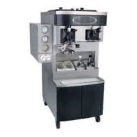
Model C602
Interface Boards
Both interface boards are the same for the shake
and soft serve side. Ribbon cables provide the
communication path between the UVC3 and the
interface boards.
A 16 VAC transformer supplies the power for the
interface boards at Terminals A and B. Each board
has a 5 VDC output terminal block. Line voltage is
connected to the interface boards (L1 and L2) to
operate components in the machine on command.
There are four sets of pins (W2,W3,W4,W5) on
each interface board. The pins on the soft serve
board are inactive in the Model C602. The pins on
the shake interface board function as follows:
W2 Installing a jumper resets the Brush Clean
date when both sides are in the OFF mode.
W3 If the machine is in the AUTO mode,
installing a jumper will simulate the viscosity
setpoint.
W4 Installing a jumper forces the start of the
glycol pump and both left and right glycol
solenoid are energized.
W5 If a jumper is present the real time clock can
be changed in any mode.
Personality Boards
A Personality Board plugs into the interface board.
The shake proximity sensor (torque coupling sensor)
and the portion control pyro-electric board harness
are connected to the shake personality board. The
soft serve personality board monitors the amperage
in one leg of power supplied to the beater motor.
Control Panel Interface Board
The Control Panel Interface Board (Dec Plate PCB)
is fastened to the back of the tempered glass panel
and communicates with the UVC3 through a USB
cable.
The control panel has two 5 VDC power leads
supplied to the board. One connection supplies
power to operate the touch sensors and LED’s and
the other 5 VDC connection provides power to
communicate with the UVC3 control.
The Vacuum Fluorescent Display (VFD) plugs into a
socket on the interface board. The potentiometer
dial at the top of the board is non-functional. The
VFD does not require a contrast adjustment.
Pins labeled W1 on the face of the Control Panel
Interface Board must have a jumper installed to
enable the audible tone when a key is selected. (W1
is located next to the audible tone device, below the
5 VDC connectors.)
The interface board must have the insulator installed
to shield the circuitry on the back of the board. The
metal rectifier guard must be installed to shield the
interface board from electrical noise.
Motor Speed Contro l
The motor speed control is powered by 5 VDC and
receives data bit information through a 10 pin ribbon
cable. The speed control transmits a modulated
signal to the syrup motor, therefore the voltage
cannot be accurately measured with a meter.
The syrup pump motors run at maximum speed in
the prime mode.
The UVC3 Control calculates the motor speed
setting in the syrup calibration mode and sends the
information to the speed control.