5
Models QS11 & QS23 To the In staller
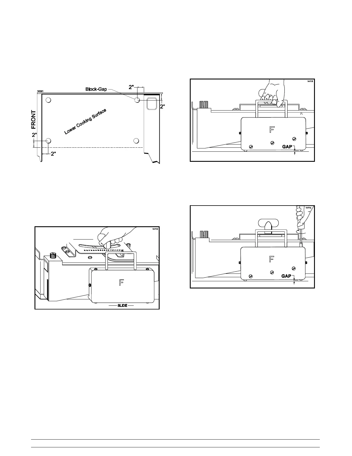
Step 4
For each cook surface requiring adjustment, place the
four gap blocks on the cook surface, approximately 2”
(51 mm) in from each corner . (Figure 5)
Figure 5
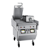
Step 5
Lower the cook surface assembly. Loosen and slowly
move the T-handle to the left until the gap
indicator/pointer is at #8 on the gap indicator plate, and
tighten the T-handle.
Figure 6
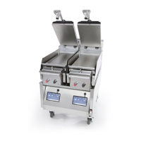
Step 6
Wearing proper protection, carefully attempt to raise
the gap slide to evaluate which gap pin is in need of
adjustment.
Figure 7
With the gap slide raised, slowly turn the gap pin
needing adjustment until it makes contact with the
cook surface. Note: Do not use force to adjust the pins.
Repeat these steps for both gap slides.
Figure 8
Step 7
Raise the upper cook surface and remove the four gap
blocks.