Overview and connections
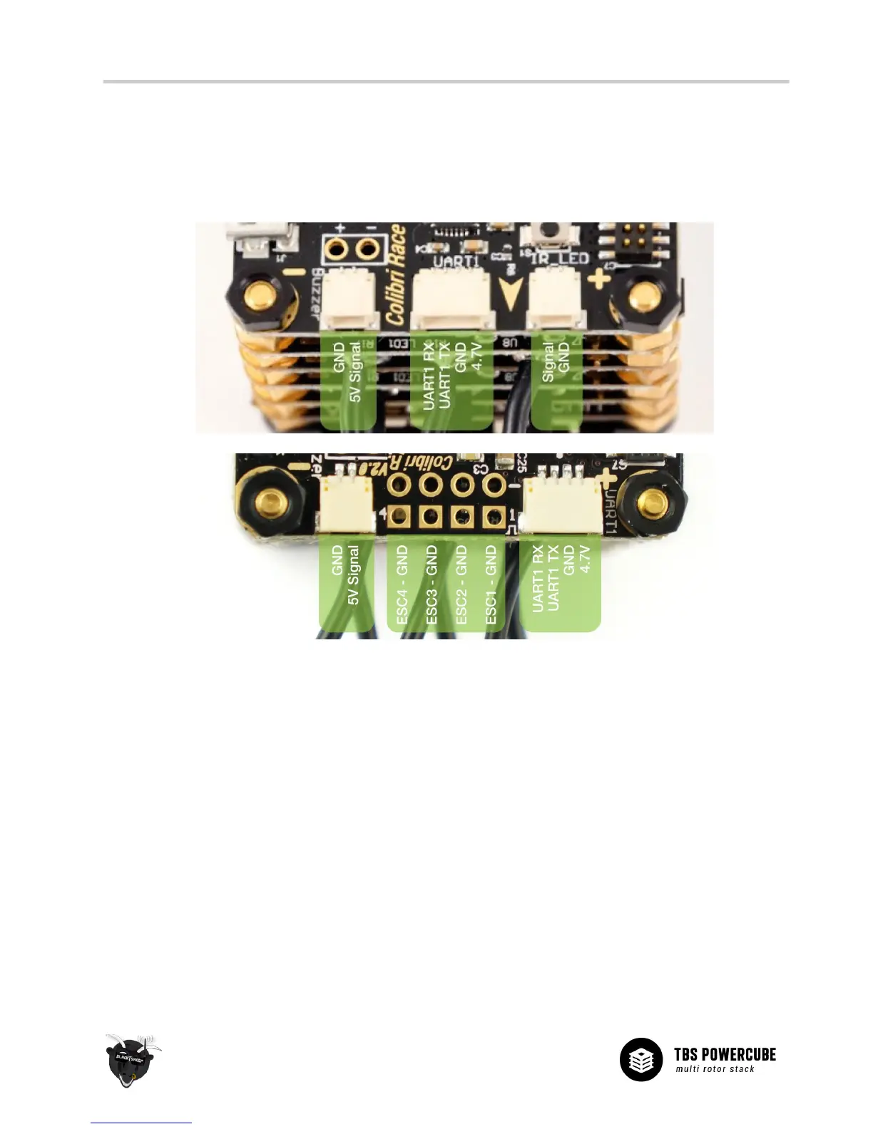
An overview of all the ports provided by the COLIBRI RACE flight controller is shown in the illustration below.
Connect your peripherals according to your requirements. Pin-out is also printed on the underside of the PCB.
North
V1:
V2:
• Buzzer - Accepts any active driven buzzer on 5V, alarms can be set in CleanFlight/BetaFlight GUI
Pin-out from left: GND / 5V Buzzer Signal
Additional soldering pads for direct soldering (first batch has reverse signed + and - pads!)
• ESC Outputs (V2) - Control signal output connector for 4 ESCs
Pin-out from left: ESC4&GND / ESC3&GND / ESC2&GND / ESC1&GND
These are not used when part of the TBS POWERCUBE, then there are pads on the PDB V2
• UART1 - Serial communication port
Pin-out from left: UART1 RX / UART1 TX / GND / 5V
• IR_LED (V1) - IR LED use for lap timing
Pin-out from left: Signal / GND
• Boot button (V1) - Boot button for flashing new firmware
Button must be pressed to get into the DFU firmware loader mode