______________________________________________________________________________________________________________________________________________________________________________
__________________
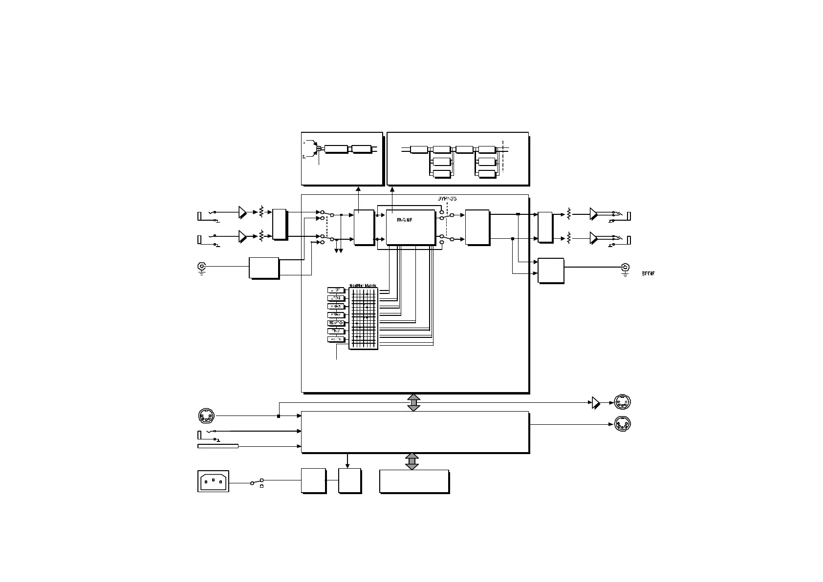
Block Diagram
The block diagram in figure 7 gives a quick view of the signal flow in the G-Force.
As the block diagram shows the input and output sections will always be active, even in Bypass mode.
SPDIF
ANALOG
INPUTS
[unbalanced]
L
DIG.
RECEIVER
R
DIGITAL
INPUT
LEVELS INPUT
GAIN
OUTPUT
GAIN
OUTPUT
A/D
D/A
DIGITAL SIGNAL PROCESSOR & DARC
INPUT
SELECTOR
MIDI IN
POWER SWITCH
OFF
ON
PEDAL IN
PCMCIA
slot
AC
POWER
MIDI OUT
MIDI THRU
BUFFER
G-FORCE FRONT
POWER
SUPPLY
STAND
BY
MIDI & PEDAL
(from CPU)
Input level
sense
CHO
SPK FLT
Output
[balanced]
GATE TUNER
Input
I/O SETUP
Input
Fig. 7: Block diagram for the G-Force
 Loading...