______________________________________________________________________________________________________________________________________________________________________________
_________________
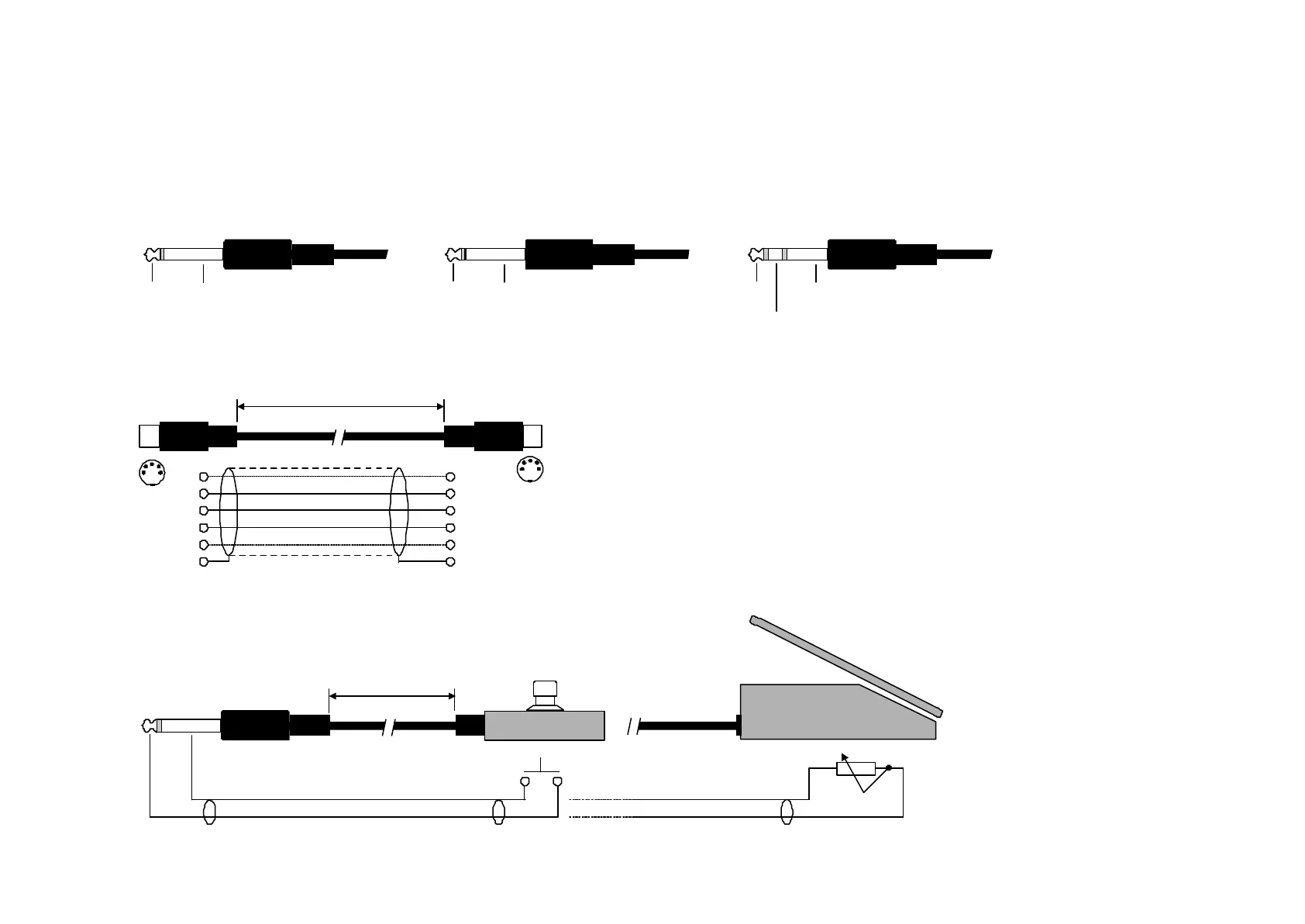
Cable Specifications
DIN CONNECTOR
JACK PLUG
JACK PLUG JACK PLUG JACK PLUG
For connection to Unbalanced inputs For connection to Balanced inputs
PEDAL SWITCH
or similar
EXPRESSION PEDAL
or similar
MIDI CABLE
EXTERNAL CONTROL CABLE
DIN CONNECTOR
Note: Pin 1 and 3 are reserved for optional RS485 interface
Therefore, use only 3-wires if the G-Force is connected to other equipment that use these pins
max. 15m
max. 100m
5 POLE - MALE
45 degrees
MONO - MALE
Ø 6.35mm, 1/4“
MONO - MALE
Ø 6.35mm, 1/4“
MONO - MALE
Ø 6.35mm, 1/4“
STEREO - MALE
Ø 6.35mm, 1/4“
5 POLE - MALE
45 degrees
SHIELDED CABLE ( 3 or 5 wires + shield )
1 wire + shield
1 1
see note
see note
4 4
2
shield/ground
Shield
ground
Shield
ground
Shield
ground
2
5
Tip
Tip
Signal
Tip
Signal
Tip
Hot +
Ring
Cold -
Switch can be momentary
or alternating type
5
3
C C
3
 Loading...