______________________________________________________________________________________________________________________________________________________________________________
__________________
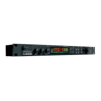
Power On Sequence
The table below shows the Power On Sequence for main board version PC13002-2, when the G-Force is switched on by using the power switch at the back panel. Equal sequence numbers mean
that the events are independent of each other. The column named Trouble Shooting has hints about what to check if the event fails.
No Event Trouble shooting
1a SB_VCC (POWER_SB, Violet wire) goes to approx. 5VDC and supplies IC1. Power cord, DZ1, IC1 or power supply.
1b +15V (POWER_+15V, Orange wire) goes to approx. +15VDC. power supply, load (normal current load is approx. ?mA)
1c -15V (POWER_-15V, Yellow wire) goes negative to approx. -15VDC. power supply, load (normal current load is approx. ?mA)
2 TP4 goes to +4.7VDC. C8 is discharged and keeps IC1 pin 13 low and subsequently
IC1 pin 8 goes high.
IC1, DZ1
3a +5VSB, (+5V_STANDBY*, Brown wire) goes to approx. +3.2VDC R7
3b Q1 and Q2 turns on IC2 Q1, Q2, IC2
3c Standby LED is lit Q1, Q2, IC2
4a +5V (POWER +5V, Red wire) goes high. power supply, load (normal current load is approx. ?A)
4b TP1, -15V starts up. IC2
4c TP2, +15V starts up. IC2
5a Display backlight turns on Ribbon cable at Front connector J1, two solderings at display for back light.
5b IC9 pin8, CPU clock starts up, 14.112MHz IC9, X1, (unstable until clean power comes from IC27)
5c IC27 pin2+3+6+7, power for PLL, goes high. IC25, IC27
5d TP68, 256FS starts up IC9, IC28 + soldering, If CPU clock is missing the frequency is undefined.
5e LD4 turns on. IC33. NOTE: If IC35, 36 or 41 are defective they can turn LD4 off via IC33 !!
5f Q8 emitter, +5VA (+5VAD) starts up. IC26, Q8
5g IC37 pin2, +5VA (+5VDA) starts up. IC37
5h TP3, rises to +3.3V . IC42
6a TP8, DSP clock starts up, 44.100KHz IC24 + soldering
6b TP70, ADA_64FS starts up (2.822MHz) IC24 + soldering
6c TP72, ADA_1FS starts up (44.1KHz) IC24 + soldering
 Loading...