______________________________________________________________________________________________________________________________________________________________________________
__________________
LED Error Codes
LD1 LD2 LD3 Code explanation Comment
off off off Normal At power on all LEDs will blink once.
on on on Checksum error in boot software Reload boot software
LD4 has two functions: 1: Show power on. 2: Defines the voltage named +5VDA (+5.5VDC)
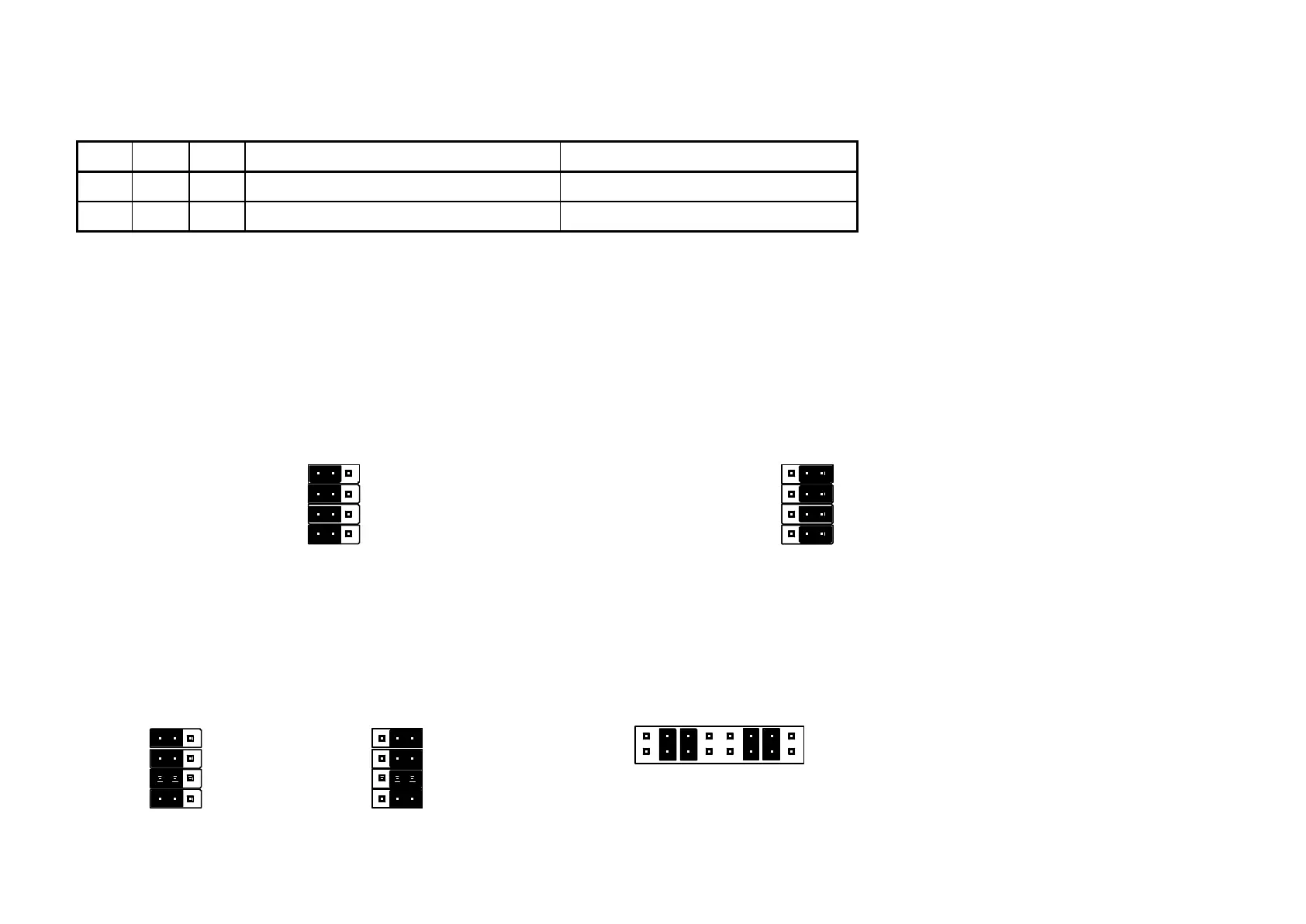
Jumper settings
Main board version PC13002-2:
J7, (JTAG) is unused. JP3, JP4, JP5 & JP6 controls boot mode:
JP3
JP4 JP4
JP5 JP5
JP6 JP6
JUMPER SETTING:
Boot from Flash (normal mode)
Boot from PCMCIA (only used at factory)
Main board version PC13002-4:
J12 and JTAG are unused. JP3, JP4, JP5 & JP6 controls boot mode:
JP3 JP3
JP4 JP4
JP5 JP5
JP6 JP6
Boot from Flash
(normal mode)
Boot from PCMCIA
(only used at factory)
J11
 Loading...