______________________________________________________________________________________________________________________________________________________________________________
__________________
Disassembly Procedure for Front Section
1. Turn Off Power and Disconnect Power Cord.
2. Loosen 5 screws, see fig. 1, and remove the top cover.
3. Disconnect front connector J1, see fig. 2.
4. Remove side panels by unscrewing 4 screws at each side, see fig. 4.
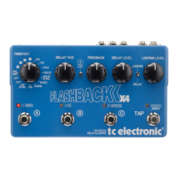
Top view
4 screws
Fig. 4: Screws at side panels.
5. Remove the front section.
6. Pull off the PARAMETER and VALUE knobs by hand.
7. Place the front profile horizontally with the buttons facing down. Place the
profile on some stand-off to avoid any pressure on the push buttons.
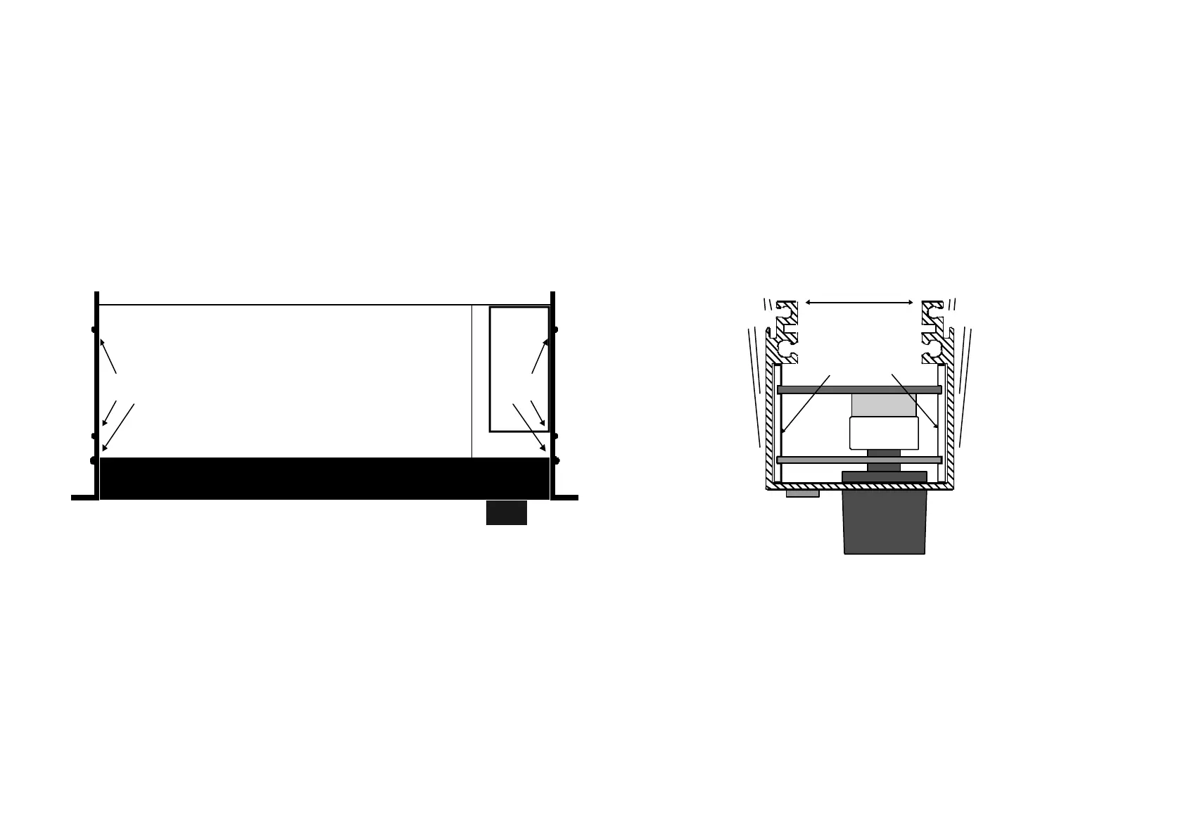
8. At the end with PARAMETER and VALUE knobs, pull out the two white PCB
guides. Opening up the profile a little will lighten the pressure at the PCB
guides, see fig. 5.
Note: All push buttons are loose in the profile after removing the guides.
9. Use the ribbon cable to lift up the front board assembly a little and then slide it out
gently at the end with PARAMETER and VALUE encoders. The shafts of the
encoders can just pass the profile in this way.
Press out a little
PCB
guides
Fig. 5: Front profile shown from VALUE end.
 Loading...