IM-995
Installation, Operation & Maintenance Manual
20
Optional Accessories (cont.)
Oil Circulation Systems:
a. Use non-detergent, turbine grade oil specified on the general accessory drawing.
b. Utilize the drain ports specified on the general accessory drawing.
c. There must be a slope of 15 degrees or ½" slope per foot to effectively drain the bearing and minimize leakage.
e. Piping must be flushed to leave no residue on a 20 micron filter.
f. Return piping should be heat traced to maintain flow in cold conditions.
i. If a heat slinger is supplied, place vanes facing away from the bearing to prevent oil from being drawn out of the bearing.
leakage. Oil flow rate is found on the general assembly drawing.
9. Site-Feed Oilers — Fans provided with optional, site-feed oilers, the oil level is to be set as indicated by the manufacturer’s
installation instructions provided with the fan.
10. Concrete Filled Bases:
Inertia Bases
instructions are a guide for filling a base with concrete. Remember to use safe practices when filling concrete into the base. It is
best to fill concrete at or near the base’s final resting area to reduce injury while transferring to the permanent location. The surface
of the concrete must be to the height of the top of the isolation base, +0.06" or - 0.125", so the pedestal can set on the isolation
base with proper support. The mounting surface at the top of the base should be kept clean to ensure secure fastening between
the base and the bottom of the fan.
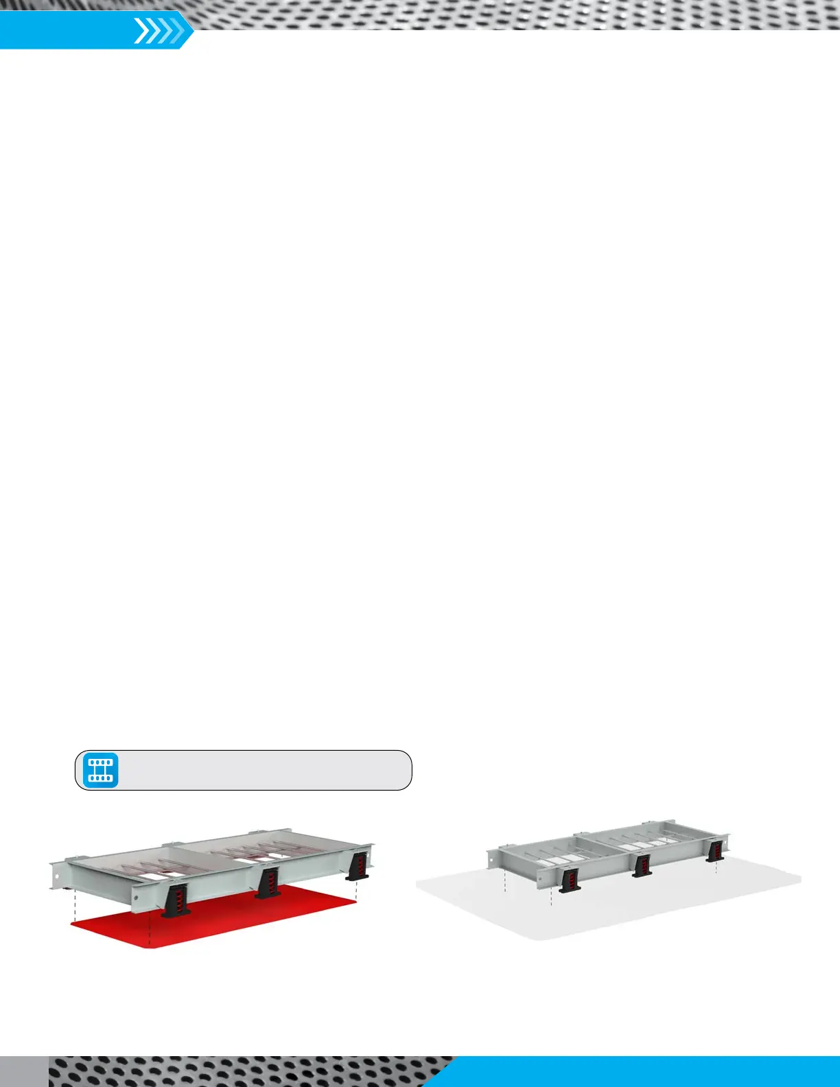
An inertia base is supplied with steel mesh or rebar added within the base frame with the intent of being filled with concrete and
When an optional bottom pan is supplied from the factory, the base must be set on a flat, level surface with the bottom pan
directly on the surface fully supporting the pan to maintain flatness on the bottom side. Pour concrete into the base and remove
excess concrete on the top side of the base to maintain an even mounting surface for fan mounting. Be sure that the concrete
has cured before lifting the base. Install isolators per the isolator installation manual.
When the optional bottom pan is not supplied, the base must be set on a flat, level surface that can fully support the weight of
the concrete. Place a sheet of heavy-mil poly-film between the flat surface and the base frame. Pour concrete into the base and
remove excess concrete on the top side of the base to maintain an even mounting surface for fan mounting. Be sure that the
concrete has cured before lifting the base. Install isolators per the isolator installation manual.
Optional Bottom Pan
Plastic Sheeting
Click To View Our
Inertia Base Installation Video