Installation, Operation & Maintenance Manual
IM-995
9
Fan Installation – Factory Assembled Units (refer to lifting/safety section)
All fan impellers are statically and dynamically balanced using state of the art equipment in the factory. Final trim balancing is
performed on factory assembled fans, unless the specified electrical characteristics of the motor are outside the limits of the factory
test equipment. If the motor and drives are supplied, the complete assembly is run tested and balanced. Infrequently, fans are
supplied with unusual electrical characteristics and cannot be tested with the motor. In this situation the fans are run and balanced
using a factory driver. Likewise, if motors and/or drives are not supplied, the fan is tested with the factory driver. Final balancing, at
the buyer’s expense, should be performed in the field after the motor and/or drives are installed. This service is available from TCF,
otherwise this should be entrusted to a qualified technician.
Follow proper handling instructions as given earlier.
1.
2. Remove skid, crates and packing materials carefully.
3. If vibration isolation is to be used, place isolation base on
mounting bolts. Line up holes in fan base with bolts. See Item
10 in the "Optional Accessories" section for preparing inertia
bases for use.
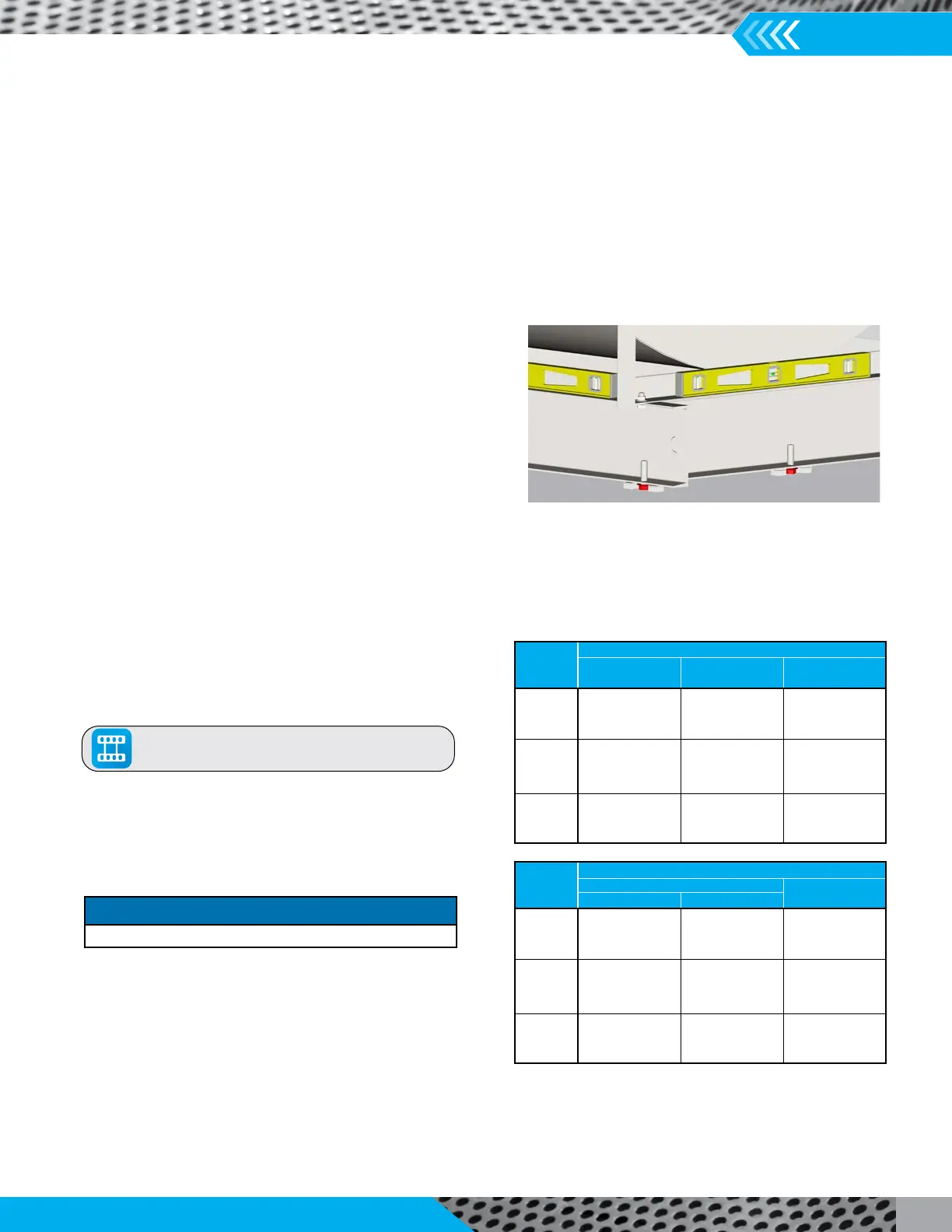
4. Place the fan on mounting structure. Carefully level the unit
as necessary using stainless steel shims on both sides of each
anchor bolt. Back off leveling nuts if used. Be careful not to
force the fan to the mounting structure/foundation. This may
cause the bearings to become misaligned or pinched causing
vibration and premature failure.
5. Check the alignment of the bearings. Shim or reposition the
bearings if necessary.
6. Check alignment of sheaves on belt driven fans.
7. Check tension of belts to see if it is sufficient. Sheaves on
belt driven fans are often provided with taper lock bushings.
When tightening bushing bolts, proceed in a progressive
manner to avoid cocking the tapered surfaces between the
bushing and the sheave. Torque per tables on the right.
8. Check alignment of factory mounted couplings, as they are
subject to misalignment during shipment and installation.
Realign to within 0.002" offset and parallel. Allow for
thermal growth of the motor by setting the motor 0.001"
low for each inch of shaft up to 0.005."
9. Check the tightness of the impeller on the shaft. Check the
tightness of foundation bolts, motor bolts, sheaves and
the impeller-inlet cone clearances and overlap are correct.
10. Check that bearings are fully lubricated and check the
oil level in the static oil lube systems. For spherical roller
bearings with split pillow block housings, the bottom half
of the housings should be 1/3 full of grease. For oil lube
bearings, the oil level should reach the midpoint of the
bottom roller or ball.
11. Install any accessories shipped loose from the factory.
The above torque values are for nonlubricated fasteners and Browning
Bushings. For bearing set screws, use manufacturer’s recommendations.
If other bushings are used, utilize bushing manufacturer's specifications.
Tolerance: +/-
5%
For impeller set screws use Grade 2 values.
SIZE
FASTENER - TIGHTENING TORQUE (Ft. Lbs.)
GRADE 2 GRADE 5 GRADE 8
#10 — — —
1
4-20 5.5 8 12
5
16-18 11 17 25
3
8-16 22 30 45
7
16-14 30 50 70
1
2-13 55 75 110
9
16-12 — — —
5
8-11 100 150 220
3
4-10 170 270 380
7
8-9 165 430 600
1-8 250 645 900
1
1
4-7 500 1120 1500
SIZE
TAPER BUSHINGS - TIGHTENING TORQUE (Ft. Lbs.)
SPLIT
QD
FOR DRIVE
IN IRON IN ALUM. HUB
#10 — — 6
1
4-20 7.9 7.5 9
5
16-18 16 13 15
3
8-16 29 24 30
7
16-14 — — —
1
2-13 70 — 60
9
16-12 — — 75
5
8-11 140 112 135
3
4-10 — — —
7
8-9 — — —
1-8 — — —
1
1
4-7 — — —
Tightening Torque
Carefully level the fan on the foundation
Click To View Our
Sheave Installation video
NOTICE
Most couplings need lubrication.