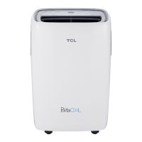
Do you have a question about the TCL TAC-12CHSA/XA71 and is the answer not in the manual?
Explanation of the remote controller buttons and their functions, including mode, fan, and temp controls.
Details on various safety protection mechanisms within the electronic controller, like voltage and overcurrent.
Information on how protection and failure codes are displayed on the unit.
List of failure types, LED codes, and digital LED codes for troubleshooting.
List of protection types and their corresponding function indicators and digital LED codes.
Safety rules and recommendations for the installation of the air conditioner unit.
Safety rules and recommendations for the proper use and maintenance by the user.
Key safety rules and prohibitions to follow during operation and maintenance.
Troubleshooting steps for specific error codes like E1, E2, E6, E3, E7, E8, E0, E5.
Flowchart for diagnosing defective outdoor unit IPM or compressor issues.
Flowchart for diagnosing and resolving DC Over Current errors.
Detailed troubleshooting steps for E0 and E5 errors.
| Brand | TCL |
|---|---|
| Model | TAC-12CHSA/XA71 |
| Category | Air Conditioner |
| Language | English |


 Loading...