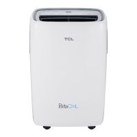
Do you have a question about the TCL TAC-12CSD/XA81I and is the answer not in the manual?
Detailed electrical diagrams for indoor and outdoor units.
Schematic showing electrical connections for indoor and outdoor units.
Layout diagrams for indoor unit PCBs (A010268, A010283).
Overview of various protection modes for the air conditioner.
Step-by-step guide for installing the air conditioner unit.
Troubleshooting flowcharts for various error codes.
Troubleshooting flowchart for IDU and ODU communication failure (E0).
Troubleshooting flowchart for IDU room/coil temperature sensor failures (E1, E2).
Troubleshooting flowchart for AC cooling system abnormalities (E4).
Troubleshooting flowchart for IDU ventilation failure (E6).
Troubleshooting for ODU sensor failures (E3, E7, E8).
Troubleshooting flowchart for ODU IPM or compressor drive faults (E9).
Troubleshooting flowchart for ODU DC fan motor failure (EF).
Troubleshooting flowchart for ODU voltage test sensor failure (EU).
Troubleshooting flowchart for IPM overheat or overcurrent protection (P0).
Troubleshooting flowchart for over/under voltage protection (P1).
Troubleshooting flowchart for over current protection (P2).
Troubleshooting flowchart for ODU discharge temperature overheating (P4).
Troubleshooting flowchart for sub-cooling protection in cooling/dry mode (P5).
Troubleshooting flowchart for ODU overheating protection in cooling mode (P6).
Troubleshooting flowchart for IDU overheating protection in heating mode (P7).
Troubleshooting flowchart for outdoor ambient over/under-temperature protection (P8).
Troubleshooting flowchart for compressor driving protection (P9).
Troubleshooting flowchart for cooling system gas flow abnormal protection (F4).
Troubleshooting flowchart for PFC overcurrent protection (F5).
Troubleshooting flowchart for compressor phase/anti-phase protection (F6).
Troubleshooting flowchart for module temperature protection (F7).
Troubleshooting flowchart for 4-way valve reversing abnormal (F8).
Troubleshooting flowchart for gas leakage protection (Fy).
| Type | Split AC |
|---|---|
| Cooling Capacity | 12000 BTU/hr |
| Cooling Capacity (Tons) | 1 Ton |
| Refrigerant | R32 |
| Compressor Type | Rotary |
| Power Supply | 220-240V, 50Hz |
| Operating Temperature (Cooling) | 18°C to 43°C |
| Functions | Auto Restart, Sleep Mode, Timer |
| Noise Level (Indoor Unit) | 38 dB(A) |


