31
Section IV – Pipeline Under Pressure
2.0 Continued 2.3 Calculating the Travel Distance
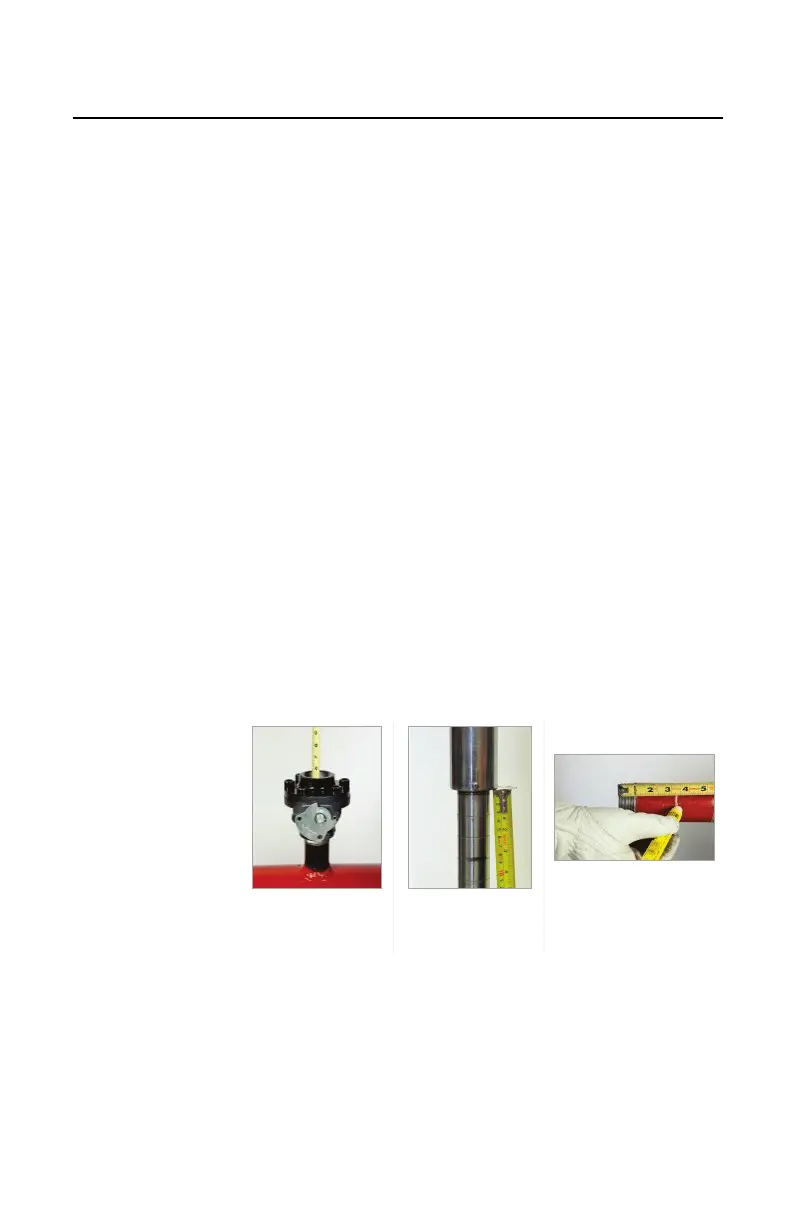
Determine the distance the PIG-SIG V needs to
travel to be completely set in the tapping fitting. With
the boring bar fully retracted and the feed tube at the
zero mark on the body tube (Figure 4.14), measure
the following:
A. Measurement “J” is the distance from the top of
the plug assembly fitting to the top of the valve
face (Figure 4.15). This distance was measured
and recorded before the tap was made.
B. Threaded Valves: With the PIG-SIG fully
retracted, measure from the bottom of the feed
tube to the mark made on the body tube (Figure
4.16).
Flanged Valves: With the PIG-SIG fully
retracted, measure from the bottom of the feed
tube to the mark made on the body tube (Figure
4.16). This is Measurement “G.”
C. Threaded Valves: Transfer the measurement of
the bottom of the feed tube to the mark on the
body tube. Measure from the end of the adapter
threads and mark this on the outside (Figure
4.17).
Measurement “J”
Measurement
Adapter
 Loading...