45
Section IV – Pipeline Under Pressure
3.0 Continued
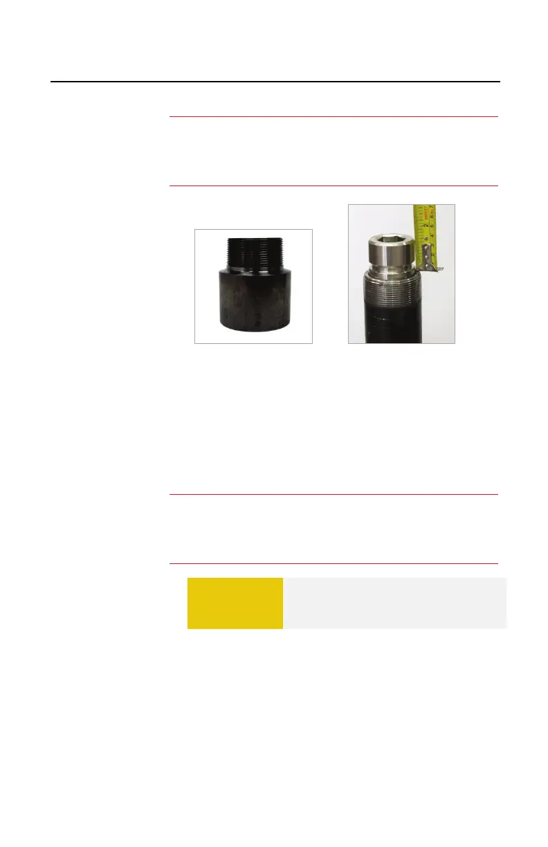
Figure 4.47. Optional Adapter
Figure 4.48. Installed Plug
3.4 Installing the Drilling Machine
A. Apply thread paste (pipe dope) on the threaded
drilling machine adapter (Figure 4.49).
B. Install the drilling machine on the valve.
Flanged Valves: Install a new gasket.
C. Threaded Valves: Tighten the drilling machine
assembly wrench-tight. Apply the pipe wrench to
the adapter only (Figure 4.50). Do not apply the
wrench to the drilling machine.
D. Threaded Valves: Measure from the face of the
valve to the mark made on the adapter (Figure
4.51) Record this as Measurement “M”.
:
An optional spacer may be installed to provide clearance to
reduce the risk of valve contact with the plug body
(Figures
.
:
-psi working pressure, use a new
or equal gasket on all connections.
Flanges, use a new RTJ gasket.
CAUTION
Do not over-tighten the drilling
machine. Do not let the tapping valve
rotate during tightening.
 Loading...